3: Installation
3-6
UPS469-01-00 PowerWAVE 3000T User Manual Dated 05-04-13
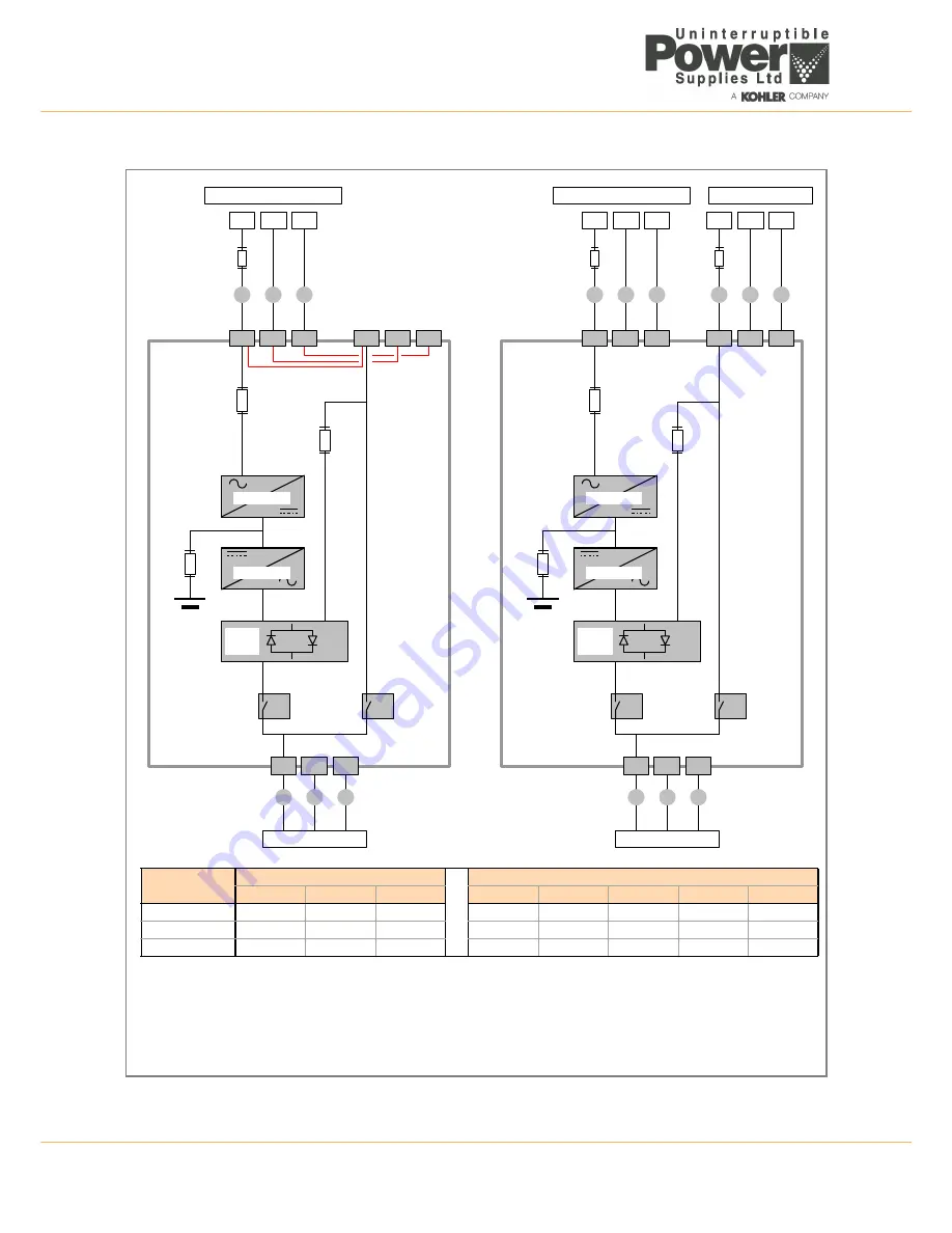
Figure 3.3 Single phase input wiring details
Fus
e
A
FA1
FA2
FA3
Output
Switch
INPUT MAINS SUPPLY
PE
N
L1
OUTPUT SUPPLY
2L1
IL1
1N
PE
2N
PE
D
A
A
A
Input and bypass
terminals internally linked
for single input supply
IA2
Battery
Fuse
Input
Fuse
Rectifier
Bypass
Fuse
Inverter
Static
Switch
3L1
3N
PE
D
D
Maint.
Bypass
Switch
Fus
e
B
FA1
FA2
FA3
Output
Switch
INPUT MAINS SUPPLY
PE
N
L1
OUTPUT SUPPLY
IL1
1N
PE
D
B
B
B
IA2
IA1
Battery
Fuse
Input
Fuse
Rectifier
Bypass
Fuse
Inverter
Static
Switch
3L1
3N
PE
D
D
Maint.
Bypass
Switch
Fus
e
C
BYPASS SUPPLY
PE
N
L1
C
C
C
2L1
2N
PE
IA1
1.
Fuse
and Cable recommendations to IEC 60950-1:2001
2.
The fuse and cable rating details in the above tables are a recommendation only.
3.
The UPS must be installed to prescribed IEC or local regulations (e.g. BS7671:2008).
4.
External DC Cables and Battery fuses are bespoke to the installation.
Power (kVA)
SINGLE INPUT FEED
DUAL INPUT FEED
Fuse A
Cable A
Cable D
Fuse B
Cable B
Fuse C
Cable C
Cable D
7.5
1 x 40
3 x 6.0
3 x 6.0
1 x 40
3 x 6.0
1 x 40
3 x 6.0
3 x 6.0
10
1 x 63
3 x 10
3 x 10
1 x 63
3 x 10
1 x 63
3 x 10
3 x 10
12
1 x 63
3 x 10
3 x 10
1 x 63
3 x 10
1 x 80
3 x 16
3 x 16
Summary of Contents for PowerWave 3000T
Page 1: ...Pioneering solutions for total power protection PowerWave PW 3000 T User Manual ...
Page 2: ......
Page 8: ...1 Safety 1 2 UPS469 01 00 PowerWAVE 3000T User Manual Dated 05 04 13 ...
Page 30: ...3 Installation 3 18 UPS469 01 00 PowerWAVE 3000T User Manual Dated 05 04 13 ...
Page 44: ...4 Operation 4 14 UPS469 01 00 PowerWAVE 3000T User Manual Dated 05 04 13 ...
Page 56: ...7 Options 7 8 UPS469 01 00 PowerWAVE 3000T User Manual Dated 05 04 13 ...


