3: Installation
3-8
UPS469-01-00 PowerWAVE 3000T User Manual Dated 05-04-13
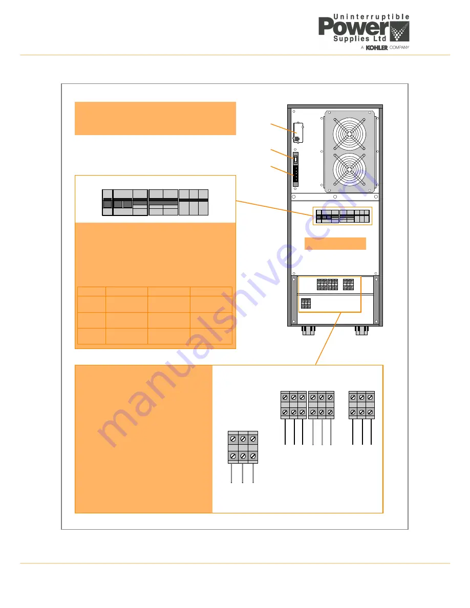
Figure 3.5 Cabinet A fuse and connection details (rear view) – single phase input
+
–
N
3L1
3N
PE
PE
PE
2L1
2N
1N
1L
1
External Battery
(
**
option)
Mains
Supply
Bypass
Supply
(
*
dual feed
Output
to Load
SNMP
JD1
X1-X21
Customer Interface Connections
JD1 – Smart Port RS232 (Sub-D9P/F).
X1-X21 – Dry Port volt-free contacts on terminal block.
Power Switches & Fuses
IA1 – Maintenance Bypass Switch
IA2 – Output Switch
FA2 – Bypass Supply Line Fuse
FA1 – Input Supply line Fuse
FA3 – Battery Fuse
FA1
FA2
FA3
7.5 kVA
50A (14x51)
Ultrafast
50A (14x51)
GL/GC
32A (10x38)
Ultrafast
10 kVA
50A (14x51)
Ultrafast
50A (14x51)
GL/GC
32A (10x38)
Ultrafast
12 kVA
50A (14x51)
Ultrafast
50A (14x51)
GL/GC
32A (10x38)
Ultrafast
IA1 IA2 FA2 FA1 FA3
only)
Input/Output Power Connections
*
In a ‘single feed’ (standard) installation
terminals 2L1 and 1L1 are linked by cables
fitted to the UPS side of the terminal blocks.
Terminals 2N and 1N are similarly linked.
When using a ‘dual feed’ supply these links
should be removed and the bypass supply
cable connected as shown in this diagram.
**
The UPS internal battery is normally
connected to the battery isolator switch (FA3).
If an external battery cabinet option is used,
the internal batteries are disconnected and
the external battery cabinet is connected to
the terminals shown in this diagram
(See Figure 3.9)
.
Cabinet Rear View
Summary of Contents for PowerWave 3000T
Page 1: ...Pioneering solutions for total power protection PowerWave PW 3000 T User Manual ...
Page 2: ......
Page 8: ...1 Safety 1 2 UPS469 01 00 PowerWAVE 3000T User Manual Dated 05 04 13 ...
Page 30: ...3 Installation 3 18 UPS469 01 00 PowerWAVE 3000T User Manual Dated 05 04 13 ...
Page 44: ...4 Operation 4 14 UPS469 01 00 PowerWAVE 3000T User Manual Dated 05 04 13 ...
Page 56: ...7 Options 7 8 UPS469 01 00 PowerWAVE 3000T User Manual Dated 05 04 13 ...


