4: Operation
4-2
UPS469-01-00 PowerWAVE 3000T User Manual Dated 05-04-13
4.2.2 Mimic
LED
indicators
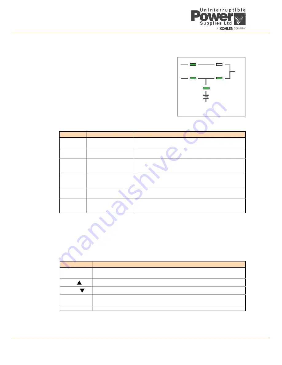
The mimic diagram indicates the UPS power flow status and the led
indicators change colour between Green, Red and OFF to indicate
the UPS operating conditions.
LINE 1
(rectifier) and
LINE 2
(bypass) indicate the availability of
the mains and bypass power supply.
INVERTER
and
BYPASS
, indicate which of the two power sources is
supplying the critical load power.
The
BATTERY
LED indicator indicates the battery availability and
flashes when the battery is supplying the load.
The
ALARM
LED indicates a detected internal or external alarm
condition and when activated it is accompanied by an audible
alarm.
LED Indication summary
4.2.3 Operator
keys
The operator keys allow the user to:
• Make settings and adjustments via the menu driven LCD display
• Start-up and shut down the UPS and transfer the load between inverter and bypass
• Monitor and display the UPS operating voltages, currents, frequencies and other values on the LCD
display
Key function summary
Indicator
Indicator Status
Interpretation
LINE 1
GREEN
RED
Mains available
Mains problem or unavailable
LINE 2
GREEN
RED
Bypass mains available
Bypass mains problem or unavailable
ALARM
OFF
Flashing RED + buzzer
RED
No alarm condition
Alarm condition detected
Alarm condition accepted (has been reset)
INVERTER
GREEN
RED
OFF
Load is on inverter (protected from mains disturbances)
Inverter fault (load is not transferable to inverter)
Inverter not operating
BY-PASS
GREEN
OFF
Load is on bypass (unprotected from mains disturbances)
Bypass not unavailable
BATTERY
GREEN
RED
Flashing GREEN
Battery OK
Battery fault or discharged
On Battery
KEYS
FUNCTION
ON/OFF
ON/OFF
Used to switch-on or switch-off the UPS
(Both keys must be pressed simultaneously for either
ON/OFF
operation).
UP
(
)
Scroll upwards through a displayed menu.
DOWN
(
)
Scroll downwards through a displayed menu.
RESET
Cancels the audible alarm. If the alarm condition was transient the
ALARM
LED will also extinguish,
otherwise it will remain
ON
(red).
ENTER
Confirms (selects) a chosen menu item.
LINE 1
LINE 2
BY PASS
INVERTER
BATTERY
LOAD
Figure 4.2
Summary of Contents for PowerWave 3000T
Page 1: ...Pioneering solutions for total power protection PowerWave PW 3000 T User Manual ...
Page 2: ......
Page 8: ...1 Safety 1 2 UPS469 01 00 PowerWAVE 3000T User Manual Dated 05 04 13 ...
Page 30: ...3 Installation 3 18 UPS469 01 00 PowerWAVE 3000T User Manual Dated 05 04 13 ...
Page 44: ...4 Operation 4 14 UPS469 01 00 PowerWAVE 3000T User Manual Dated 05 04 13 ...
Page 56: ...7 Options 7 8 UPS469 01 00 PowerWAVE 3000T User Manual Dated 05 04 13 ...


