UPS470-01-00 PowerWAVE 5000TP User Manual Dated 31-10-2011
3-9
3: Installation
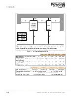
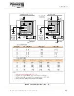
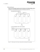
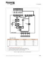
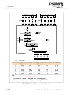
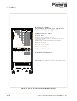
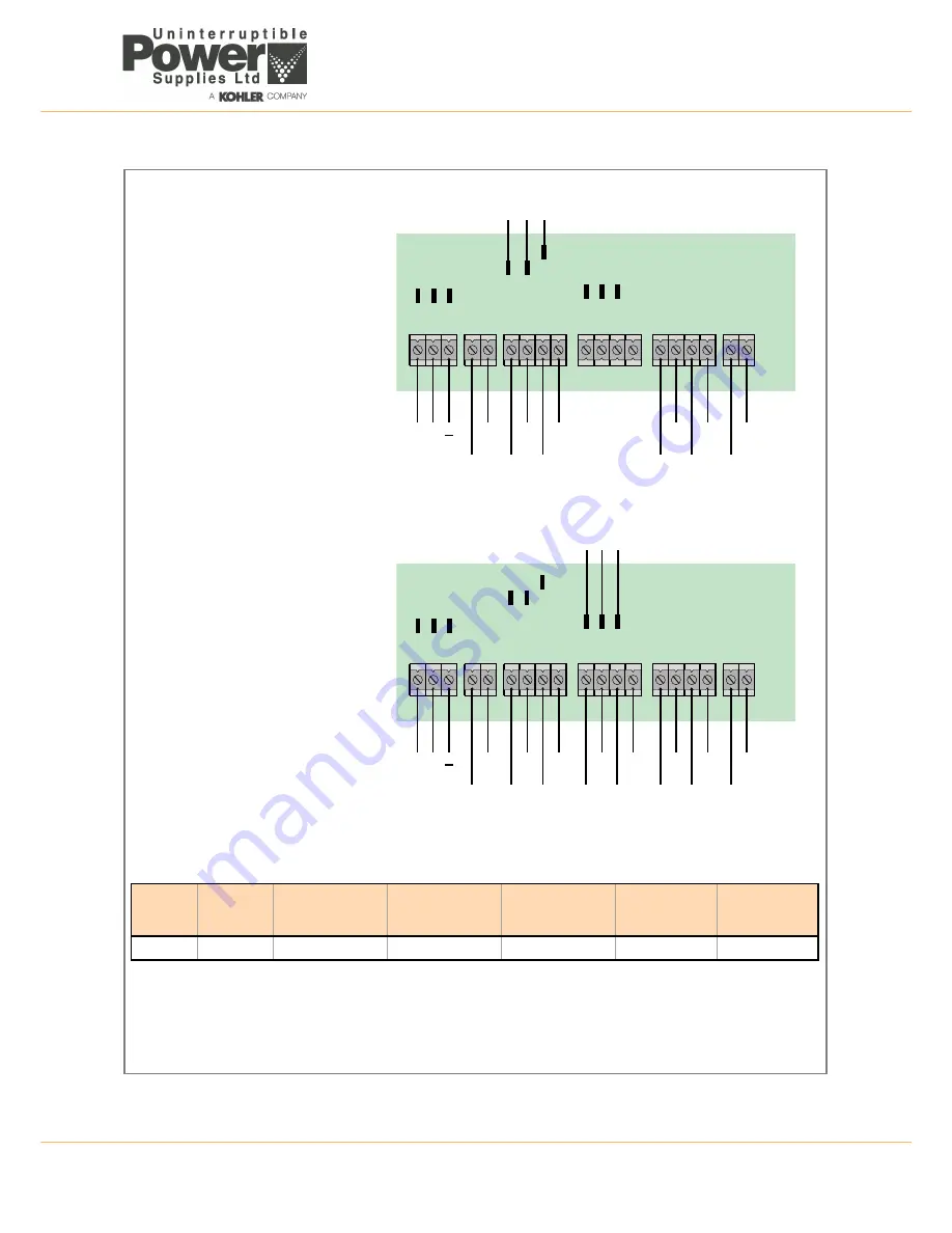
Figure 3.6 10-25kVA Connection details
1L1
3L2
3N
1L2
1L3
1N
PE
PE
PE
FA9
FA7
FA11
To Bypass Line Fuses (FA2)
FA23
FA24
FA25
PE
Ex.Batt.
Earth InputMains BypassMains UPSOutput Earth
3L1 3L3
N
+
1L1
3L2
3N
1L2
1L3
1N
2L1
2L2
2L3
2N
PE
PE
PE
FA9
FA7
FA11
To Bypass Line Fuses (FA2)
FA23
FA24
FA25
PE
Ex.Batt.
Earth InputMains BypassMains UPSOutput Earth
3L1 3L3
N
+
UPS
Range
Battery
(+ / N / -)
+PE
Input Bypass
3+N
(N,2L1,2L2,2L3)
Input Rectifier
3+N+PE
(N,1L1,1L2,1L3)
Output load
3+N+PE
(N,3L1,3L2,3L3)
Max. cable
section
admissible
Tightening
Torque
(Nm)
10-25kVA
4 x 16 mm
2
4 x 16 mm
2
5 x 16 mm
2
5 x 16 mm
2
16 mm
2
1.5
Fuse and Cable recommendations to IEC 60950-1:2001
The fuse and cable rating details in the above tables are a recommendation only.
The UPS must be installed to prescribed IEC or local regulations (e.g. BS7671:2008)
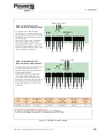
10kVA – 25kVA (Cabinets A & B)
Power Connections (Single input feed)
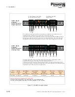
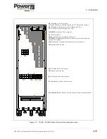
10kVA – 25kVA (Cabinets A & B)
Power Connections (Dual input feed)
For models in this power range the
external power connections are made to a
row of terminals located on the UPS Filter
Board which is accessible from the rear of
the UPS module.
Note that the Single Input configuration
requires the bypass line fuses to be
connected to FA7/FA9/FA11 on the Filter
Board. This is the standard configuration
set when leaving the factory unless a dual
input configuration is specified.
This illustration shows the connections for
a Dual input configurations, with a
separate mains supply connected to the
Bypass Mains terminals.
Note that the Dual Input configuration
requires the bypass line fuses to be
connected to FA23/FA24/FA25 on the
Filter Board. If necessary these cables will
be reconfigured by the Commissioning
Engineer as part of the commissioning
procedure.
Summary of Contents for PowerWAVE 5000TP
Page 1: ...PowerWAVE 5000 TP User Manual Pioneering solutions for total power protection ...
Page 2: ......
Page 8: ...IV UPS470 01 00 PowerWAVE 5000TP User Manual Dated 31 10 2011 ...
Page 10: ...1 Safety 1 2 UPS470 01 00 PowerWAVE 5000TP User Manual Dated 31 10 2011 ...
Page 66: ...7 Options 7 8 UPS470 01 00 PowerWAVE 5000TP User Manual Dated 31 10 2011 ...
Page 72: ...8 Specifications 8 6 UPS470 01 00 PowerWAVE 5000TP User Manual Dated 31 10 2011 ...


