3: Installation
3-14
UPS470-01-00 PowerWAVE 5000TP User Manual Dated 31-10-2011
4.
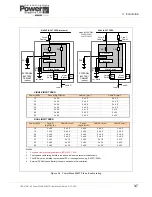
25kVA – 50kVA ‘C’ cabinet models only: Ensure the single input feed links are fitted between the input
and bypass supply terminal (see Figure 3.7).
Dual Input Feed
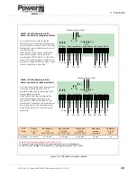
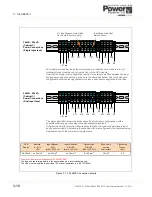
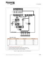
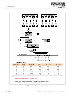
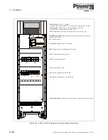
Refer to the schematic drawing and connection table in Figure 3.9.
1.
The UPS is supplied (as standard) with facilities for a single cable feed for the rectifier and bypass
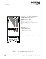
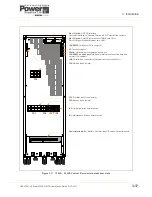
supplies. For a dual feed configuration remove the links between 1L1-2L1; 1L2-2L2; 1L3-2L3 and 1N-2N,
on the Input Terminal Block
(See Figures 3.6 /3.7)
.
2.
Connect the UPS input supply cables to terminals 1L1, 1L2, 1L3 and 1N on the UPS main terminal block
(See Figures 3.6 /3.7)
. Ensure correct (clockwise) phase rotation.
3.
Connect the UPS bypass supply cables to terminals 2L1, 2L2, 2L3 and 2N on the UPS main terminal
block
(See Figures 3.6 /3.7)
. Ensure correct (clockwise) phase rotation.
4.
Secure the cables to the fixing rail located below the connection terminals.
5.
10kVA – 25kVA Models only. Ensure the bypass cables are connected to the correct terminals on the
Filter Board (see Figure 3.6). These will be reconfigured by the commissioning engineer if necessary.
6.
25kVA – 50kVA ‘C’ cabinet models only: Ensure the single input feed links are removed between the
input and bypass supply terminal (see Figure 3.7). Leave the neutral (N) link in place.
3.7
Connecting the UPS output
3.7.1 Safety
notes
Please ensure you read and understand the following safety notes before you begin the UPS electrical
installation.
1.
All operations detailed in this section must be performed by an authorised electrician or qualified
personnel.
2.
Once the electrical installation is completed the initial UPS start-up must be performed by qualified
personnel authorised by the manufacturer.
3.
Do not operate the UPS if there is water or moisture present.
4.
When carrying out any work on the UPS output power cables you must ensure that the UPS output is
isolated at the load supply distribution panel, and where possible locked out. Warning notices should be
posted where applicable to prevent inadvertent operation of the output supply isolators.
3.7.2 Preparation for the output cabling
Circuit breakers (or equivalent protection) must be fitted between the UPS output and load equipment to
provide additional protection to the UPS in the event of an overload or short circuit, and also provide a means
of isolating individual loads if required.
Before you start connecting the UPS output cables to the load distribution panel:
• Ensure that the potential (maximum) load does not exceed the UPS model output power rating
(OUTPUT POWER) on the nameplate.
CAUTION: The input Neutral cable must ALWAYS be connected.
CAUTION: The bypass Neutral cable must ALWAYS be connected.
WARNING:
Opening or removing the UPS-covers will create the risk of exposure to
dangerous voltages if power is connected to the UPS.
Summary of Contents for PowerWAVE 5000TP
Page 1: ...PowerWAVE 5000 TP User Manual Pioneering solutions for total power protection ...
Page 2: ......
Page 8: ...IV UPS470 01 00 PowerWAVE 5000TP User Manual Dated 31 10 2011 ...
Page 10: ...1 Safety 1 2 UPS470 01 00 PowerWAVE 5000TP User Manual Dated 31 10 2011 ...
Page 66: ...7 Options 7 8 UPS470 01 00 PowerWAVE 5000TP User Manual Dated 31 10 2011 ...
Page 72: ...8 Specifications 8 6 UPS470 01 00 PowerWAVE 5000TP User Manual Dated 31 10 2011 ...


