UPS470-01-00 PowerWAVE 5000TP User Manual Dated 31-10-2011
7-1
7
Options
7.1
Introduction
The PowerWave 5000TP UPS has the following available options:
• Remote Emergency Stop facilities
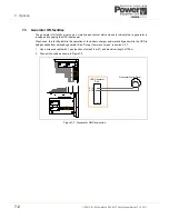
• Generator On facilities
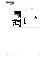
• Temperature sensor for temperature-dependant battery charging
• Software for automatic shutdown and monitoring
• SNMP Card for network management and remote monitoring
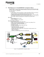
• Modem/Ethernet interface for PowerREPORTER™ management software
7.2
Remote Emergency Stop facilities
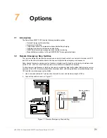
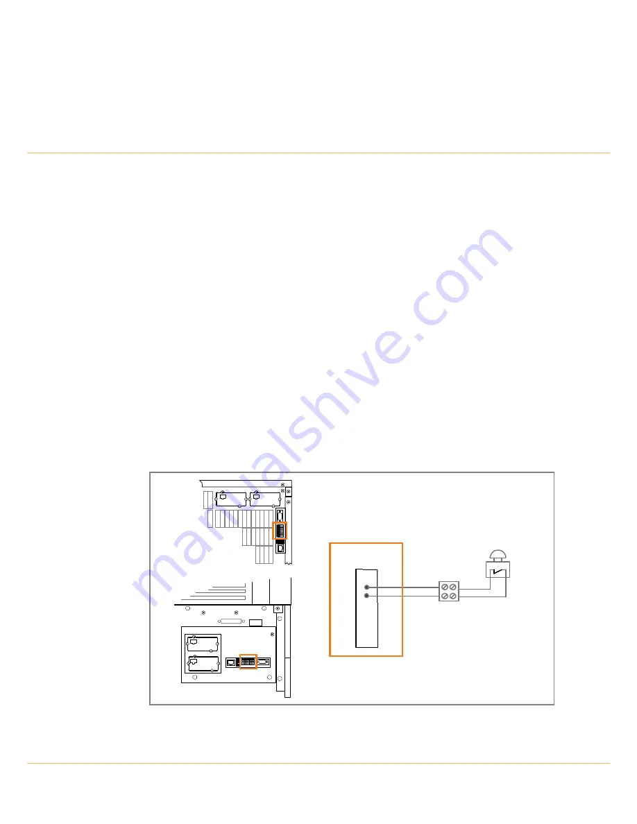
The remote emergency stop facility comprises a normally-closed contact, connected to terminal port X1/7
and X1/8 on the communications board, which opens to operate the emergency stop sequence.
Note:
Usually the remote emergency stop function is disabled, and it should be activated by a hardware code
on the
SETUP SERVICE
menu. Please contact your distributor to enable this operation.
To allow removal, maintenance or testing of any remote emergency stop facility without disturbing the normal
operation of the UPS, it is recommended that a terminal block, with linking facilities, is installed between the
UPS and the remote emergency stop button.
1.
Use a screened cable with 1 pair (section of wires 0.6 mm
2
) and maximum length of 100 m.
2.
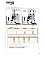
Connect the cable as shown in Figure 7.1.
Figure 7.1 Remote Emergency Stop cabling
X1
X1/7
X1/8
Remote shutdown
Terminal block
UPS Remote
Shutdown Port
Summary of Contents for PowerWAVE 5000TP
Page 1: ...PowerWAVE 5000 TP User Manual Pioneering solutions for total power protection ...
Page 2: ......
Page 8: ...IV UPS470 01 00 PowerWAVE 5000TP User Manual Dated 31 10 2011 ...
Page 10: ...1 Safety 1 2 UPS470 01 00 PowerWAVE 5000TP User Manual Dated 31 10 2011 ...
Page 66: ...7 Options 7 8 UPS470 01 00 PowerWAVE 5000TP User Manual Dated 31 10 2011 ...
Page 72: ...8 Specifications 8 6 UPS470 01 00 PowerWAVE 5000TP User Manual Dated 31 10 2011 ...

