UPS338-01-00 PowerWAVE 8000-RI DPA User Manual Dated 5 April 2013
4-9
4: Operation
4.5
Operating Instructions
Under normal operating conditions all the UPS Module in a multi-module system are running, and operating
in the ‘On Line’ (On Inverter) mode
(See paragraph 4.4.1)
.
The following procedures are provided in this section:
How to start up the UPS system and transfer the load from the Maintenance Bypass to the inverters (‘On
Line’ mode)
(See paragraph 4.5.1)
.
How to stop/start one UPS Module in a redundant multi-module system
(See paragraph 4.5.2)
How to transfer the load to the Maintenance Bypass –
(See paragraph 4.5.3)
.
How to shut down the entire UPS system
(See paragraph 4.5.4)
.
4.5.1 Starting the UPS system from the Maintenance Bypass
This procedure describes the sequence of operations necessary to power-up the UPS Module(s) whilst the
load is connected to the Maintenance Bypass supply, and then transfer the load to the UPS Inverter(s) (‘On-
Line’ mode).
Prior to powering-up the system, check and confirm the UPS system status:
• The load is supplied via the closed Maintenance Bypass switch (IA1).
• All UPS Module(s) are powered down.
Powering up the UPS Module(s):
Perform steps 1-3 below on each non-operating UPS Module.
1. Close the fused battery isolator for the UPS Module in the UPS cabinet or in the external battery cabinet/
rack, as applicable.
a) The UPS mimic panel
LINE 1
LED will be permanent green.
b) The
BATTERY
LED will be flashing green.
c) The LCD display will indicate
LOAD OFF, SUPPLY FAILURE
.
2. On the UPS mimic panel press and release both
ON/OFF
buttons simultaneously then wait 60 seconds.
a) The UPS Module will begin to power up.
b) Initially
LINE 2
LED will be red, then change to green.
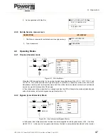
c) At this stage the LCD display will indicate
LOAD NOT PROTECTED
and the module mimic LED
indications should be as follows:
WARNING:
All the operations in this section must be performed by authorised and trained
personnel.
LINE 1
LINE 2
BY PASS
INVERTER
BATTERY
LOAD
LED
Colour
LINE 1
Green
LINE 2
Off
BY PASS
Off
INVERTER
Off
BATTERY
Green Flashing
Summary of Contents for PowerWAVE 8000DPA RI
Page 1: ...User Manual PowerWAVE 8000DPA RI Pioneering solutions for total power protection ...
Page 2: ...UPS338 01 00 PowerWAVE 8000 RI DPA User Manual Dated 5 April 2013 ...
Page 4: ...UPS338 01 00 PowerWAVE 8000 RI DPA User Manual Dated 5 April 2013 ...
Page 8: ... iv UPS338 01 00 PowerWAVE 8000 RI DPA User Manual Dated 5 April 2013 ...
Page 10: ...1 Safety 1 2 UPS338 01 00 PowerWAVE 8000 RI DPA User Manual Dated 5 April 2013 ...
Page 16: ...2 General Description 2 6 UPS338 01 00 PowerWAVE 8000 RI DPA User Manual Dated 5 April 2013 ...
Page 42: ...3 Installation 3 26 UPS338 01 00 PowerWAVE 8000 RI DPA User Manual Dated 5 April 2013 ...


