PowerWAVE 9000 DPA UPS - UPS Module Replacement
5-1
(Issue 2.1 Oct. 2009)
5
UPS Module Replacement
5.1 Replacement of UPS Module in Single Module Systems
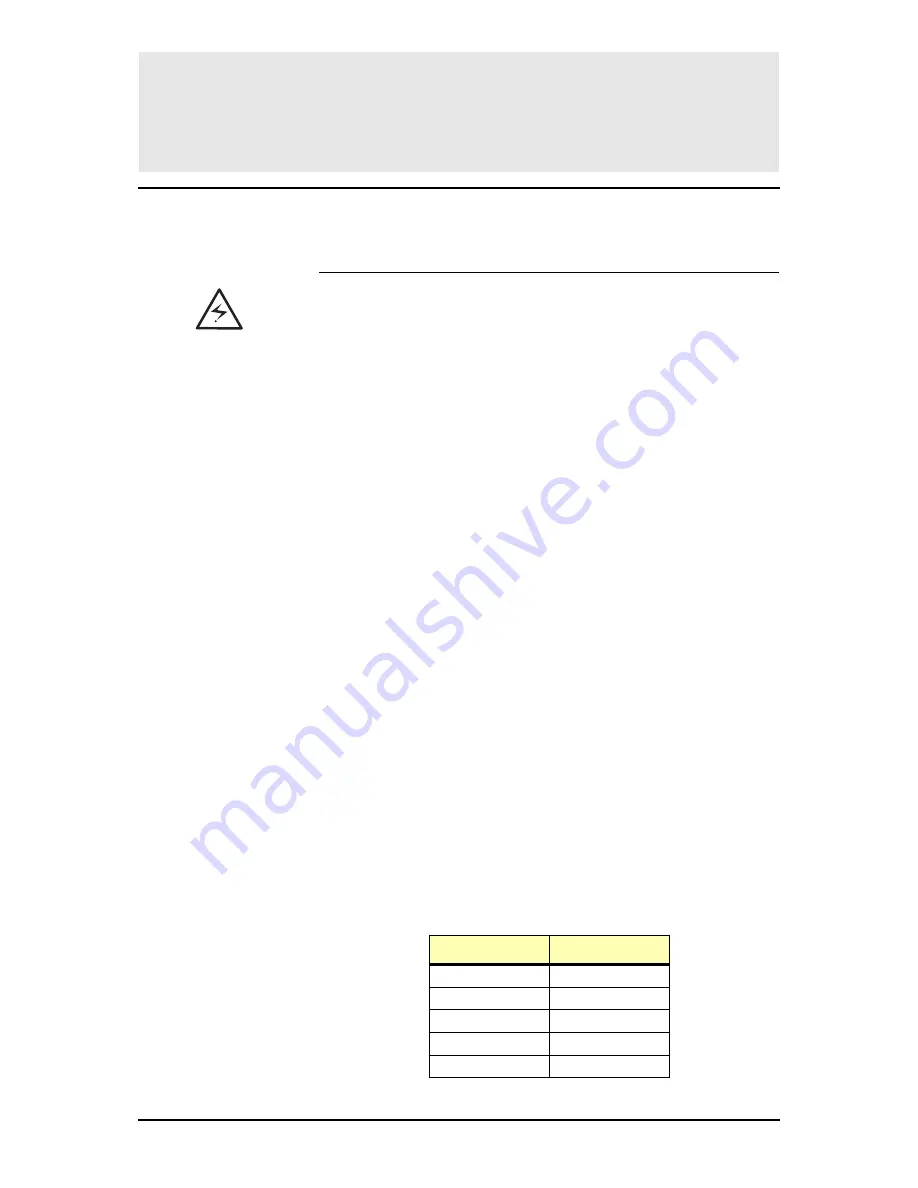
ALL THE OPERATIONS IN THIS SECTION MUST BE PERFORMED BY
AUTHORISED ELECTRICIANS OR BY QUALIFIED INTERNAL
TRAINED PERSONNEL.
BY OPENING OR REMOVING THE UPS MODULES AND MODULE
COVERS YOU RUN RISK OF EXPOSURE TO DANGEROUS
VOLTAGES!
BEFORE REMOVING A UPS MODULE MAKE SURE THE INTERNAL
DC CAPACITORS HAVE BEEN DISCHARGED FOR AT LEAST 2
MINUTES.
NEVER LEAVE THE UPS MODULE COMPARTMENT WITHOUT AN
APPROPRIATE PROTECTION COVER.
UNINTERRUPTIBLE POWER SUPPLIES LTD. WILL NOT TAKE
RESPONSIBILITY OR BE LIABLE FOR PERSONNEL INJURIES OR
MATERIAL DAMAGES CAUSED BY IMPROPER MANIPULATION OF
THE UPS, OR BY INCORRECT CABLING. THE PROPER
INSTALLATION AND USAGE INSTRUCTIONS OF THE UPS ARE
DESCRIBED WITHIN THIS MANUAL AND MUST BE STRICTLY
ADHERED TO.
5.1.1 Removing a UPS Module from a Single Module System
If your PowerWAVE 9000 DPA consists of only one single UPS Module
then perform the following steps to extract the module:
1.
Reset the Alarm on faulty Module. The audible noise will stop.
If the Alarm condition persists (the LED Indicator ALARM will
remain red) it means that there is a fault in the UPS Module.
2.
If the load is supplied by the mains in Bypass Mode (Eco-Mode) the
Maintenance Bypass (IA1) may be closed by turning it to position
“ON”.
NOTE: If the load is on inverter then before closing the Maintenance
Bypass IA1, transfer load to bypass by means of the
command “LOAD TO BYPASS” in submenu COMMANDS. On
LCD: “LOAD NOT PROTECTED” will appear.
3.
Close Maintenance Bypass Switch IA1 (position ON)
On LCD: “MANUAL BYP IS CLOSED” will appear and the LED
display will indicate as shown below:
LED Indicator
Colour
LINE 1
Green
LINE 2
Green
BYPASS
Green
INVERTER
RED
BATTERY
Green

