2: General Description
6
UPS471-02-00 PW9000DPA User Manual UK Dated 06/08/14
UPS Output (load) supply
Figure 2.3 shows that the UPS output (Load Supply) can be provided through one of three power paths depending on the
UPS operating mode:
• From the inverter (4), via the static switch and isolator IA2
• From the static bypass line (5) via the static switch and isolator IA2
• From the maintenance bypass line (6) via the maintenance bypass isolator IA1
The criteria for operating under each of these UPS modes is described below.
2.3.2 UPS Module operating modes
The diagrams in this section illustrate cabinet fitted with a single power module. Where two or more power modules are
fitted they will always adopt the same operating mode due to the parallel control logic signals.
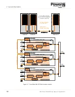
Load on Inverter
Figure 2.4 Load on inverter
This is the normal operating mode and the only one that provides the load with continuously processed and backed-up
power. In this mode, the mains supply is converted to DC by the rectifier which then charges the battery and provides
operating power for the inverter; which converts the rectifier output back to AC suitable for powering the load.
The inverter output frequency is synchronised to the bypass supply provided it remains within preset limits. If these limits
are exceeded, or if the bypass supply fails altogether, the inverter frequency control reverts to a free-running oscillator that
will produce a constant 50/60Hz UPS output.
Load on Battery
Figure 2.5 Load on battery
MAINTENANCE
BYPASS
LINE
BATTERY
Bypass
Supply
Mains
Supply
Load
Supply
IA1
IA2
INVERTER
STATIC
SWITCH
RECTIFIER
STATIC
BYPASS
LINE
PW9000
DPA
Cabinet
Charger
LINE 1
LINE 2
BY PASS
INVERTER
BATTERY
LOAD
MAINTENANCE
BYPASS
LINE
BATTERY
Bypass
Supply
Mains
Supply
Load
Supply
IA1
IA2
INVERTER
STATIC
SWITCH
RECTIFIER
STATIC
BYPASS
LINE
PW9000
DPA
Cabinet
Charger
LINE 1
LINE 2
BY PASS
INVERTER
BATTERY
LOAD


