2: General Description
8
UPS471-02-00 PW9000DPA User Manual UK Dated 06/08/14
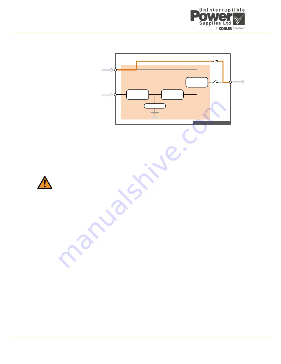
Load on Maintenance Bypass
Figure 2.7 Load on maintenance bypass
In this mode of operation the manually closed maintenance bypass switch (IA1) connects the load supply directly to the
unprocessed bypass supply. This is used to keep the load supplied (albeit without any power protection) whilst allowing
the remainder of the UPS system to be shut down for service repair.
To prevent possible inverter damage, it is important that the inverter output and maintenance bypass lines are never
connected in parallel. Therefore when transferring from the ‘load on inverter’ mode to the ‘load on maintenance bypass’
mode it is important that the load is first transferred to the static bypass (‘load on bypass’ mode) before the maintenance
bypass switch is closed.
2.3.3 UPS System operating modes
The previous section described the operating modes of the UPS power module: but UPS systems are also categorised
according to the way in which they are used at a ‘system’ level; and are typically described as being an ‘on-line’, ‘off-line’
or ‘line interactive’ UPS system. The PowerWave 9000 can be operated in all three of the above categories.
On-line operation
When used as an ‘on-line’ UPS system, the PowerWave 9000 UPS modules normally operate in their ‘load on inverter’
mode and will switch over to ‘load on bypass’ in the event of an inverter fault or overload which exceeds the system
redundancy. This will transfer the load to the static bypass without interruption (transfer time = 0).
If the transfer is due to an overload the UPS modules will switch back to the ‘load on inverter’ mode if the overload clears
and the inverter returns to normal operation. An ‘on-line’ system therefore provides the highest degree of load protection
and is always recommended if the critical load will not tolerate even a very brief supply interruption.
Off-line / line interactive operation
When the PowerWave 9000 is used as an ‘off-line’ or ‘line-interactive’ UPS system it normally operates in its ‘load on
bypass’ mode with the load being supplied through the static bypass supply; however the rectifier and battery charger are
still powered up to maintain battery charging, and the inverter section is enabled and operating on standby.
In the bypass supply fails the static switch will automatically transfer the load to the inverter within 3-5ms, and if the
rectifier input mains supply is missing when the transfer takes place the inverter will operate from battery power.
If the bypass supply returns to normal when operating with the ‘load on inverter’, the load automatically transfers back to
the static bypass (‘load on bypass’ mode) and the inverter returns to its standby function.
An ‘off-line/line interactive’ system is a slightly more efficient than an ‘on-line’ system due to the reduced rectifier/inverter
losses during normal operation and it is sometimes referred to as the “ECO” mode. However this mode is recommended
only if the connected load equipment can tolerate power interruptions of up to 3 to 5 ms during the transfer period.
WARNING:
always follow the operating instructions in this manual when starting or shutting down the UPS.
MAINTENANCE
BYPASS
LINE
BATTERY
Bypass
Supply
Mains
Supply
Load
Supply
IA2
Charger
INVERTER
STATIC
SWITCH
RECTIFIER
IA1
STATIC
BYPASS
LINE
PW9000
DPA
Cabinet


