2: General Description
12
UPS471-02-00 PW9000DPA User Manual UK Dated 06/08/14
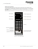
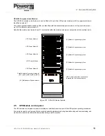
DPA-150 Component identification
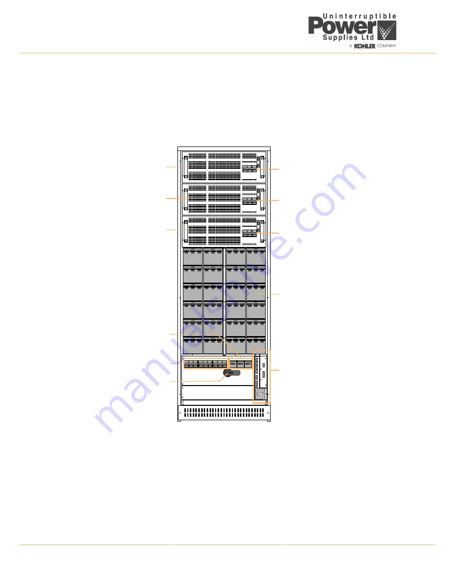
The DPA-150 can be fitted with up to three UPS power modules, with the uppermost module identified as module 1.
The battery fuses (F4) are identified with their associated power module on the panel silk-screen – e.g. F4-2 is the battery
fuse associated with module 2. The module parallel isolator switches (IA2) are similarly identified – e.g. IA2-2 pertains to
power module 2.
Note that the module input mains fuses (F1) are located within the modules and are not accessible with the module in-situ.
Figure 2.11 DPA-150 Cabinet details
[F2-2] Module 2 bypass supply fuse
Battery trays
UPS Customer Interface connections
(described in the Options chapter).
Parallel Isolator (1 per power module)
[IA1] Maintenance Bypass Isolator
UPS Power Module 1
[F2-1] Module 1 bypass supply fuse
[F2-3] Module 3 bypass supply fuse
UPS Power Module 2
UPS Power Module 3
[IA2-1] [IA2-2] [IA2-3]
Battery fuse (1 per power module)
[F4-1] [F4-2] [F4-3]


