UPS471-02-00 PW9000DPA User Manual UK Dated 06/08/14
25
3: Installation
3.6
Planning the installation (cabling considerations)
3.6.1 General requirements
The information in this section should help with the preparation and planning of the UPS power cabling.
It is the customer’s responsibility to provide all external fuses, isolators and cables that are used to connect the UPS input
and output power supplies. The UPS input and bypass terminals should be connected to the utility mains supply through a
suitable LV-Distribution board containing a circuit breaker or fused isolator to provide both overload protection and a
means of isolating the UPS from the mains supply when required. Similarly, the UPS output supply terminals should be
connected to the load equipment via a suitably fused load distribution board.
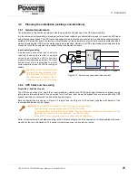
Input neutral grounding
A permanently connected input neutral is
required to enable the rectifier to operate
correctly and allow the UPS to function
properly when operating on battery. The input
neutral must also be grounded to permit
correct operation when the UPS is running on
battery.
3.6.2 UPS Cable and fuse sizing
Single feed / dual feed inputs
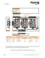
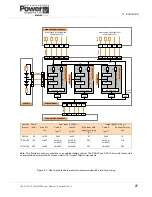
The UPS can be wired for a ‘single feed’ input (standard), whereby the UPS input supply terminals and bypass supply
terminals are internally linked; or it can be wired for a ‘dual feed’ input, where the bypass links are removed and the UPS
bypass terminals are connected to a dedicated ‘bypass’ supply.
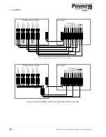
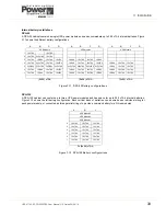
Both configurations are shown in Figure 3.3 (single feed) and Figure 3.4 (dual feed) together with details of the
recommended fuse and cable ratings
Note:
All cabinets must be cabled according to their full rated output even if the cabinet is not fully populated with power
modules at the time of installation. This allows for future expansion to be carries out safely.
Key Point:
As the input neutral must
be unswitched and connected to the
UPS at all times. DO NOT use, a 4-
pole input switch or isolator at the LV
Distribution board on a TN-S system.
Key Point:
The information in figures 3.3 and 3.4 is given for guidance only:
•
Fuse and Cable recommendations are to IEC 60950-1:2001.
•
All external fuses, isolators and power cables must be rated and installed in accordance with the
prescribed IEC standards or local regulation – e.g. BS7671:2008.
•
External DC Cables and battery fuses are bespoke to the installation.
0V
230V
UPS
Figure 3.2 Permanent, grounded input neutral

