UPS471-02-00 PW9000DPA User Manual UK Dated 06/08/14
45
4: Operation
Transferring the load to the UPS from the maintenance bypass:
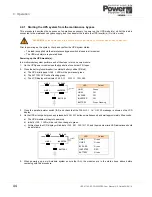
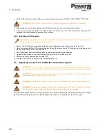
6. Ensure that the
BYPASS
LED is green (on all modules).
7. Open the maintenance bypass switch (IA1) (on all cabinets in a multi-cabinet system).
a) The LCD panels will display
MANUAL BYPASS OPEN
.
b) The
INVERTER
LED will be extinguished.
c) An audible alarm will sound.
8. Press the
RESET
button to cancel the audible alarm (on all modules).
a) The LCD display(s) will now indicate
LOAD NOT PROTECTED
.
Transferring the load to the inverter:
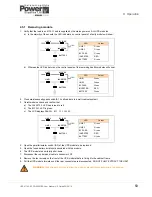
9. On the control panel (of any one module in a parallel module system):
a) Press the
UP
key once to access the menu system.
b) Use the
UP/DOWN
keys to move the cursor so that it is adjacent to
COMMANDS
then press the
ENTER
key.
c) Use the
UP/DOWN
keys move the cursor so that it is adjacent to
LOAD TO INVERTER
then press the
ENTER
key.
10. The UPS system will now transfer the load to inverter (on all modules in a parallel-module system).
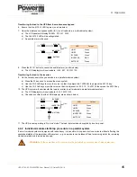
a) The LCD display(s) will now indicate
LOAD PROTECTED
.
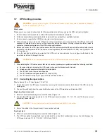
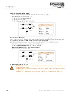
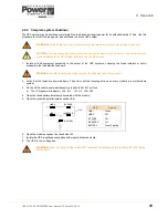
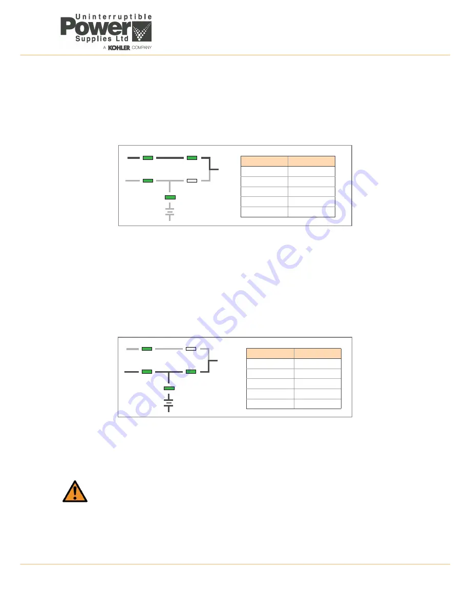
b) Check and confirm that the LED display(s) are as shown below:
11. The UPS is now operating in ‘On-Line’ mode. The load is protected and supplied by inverter power.
4.2.2 Individual module start/stop procedure in a parallel system
If a multi-module system is designed with redundancy it is possible to stop and start one module without affecting the
operational status of the remainder of the system – e.g. one module can be taken off-line for servicing whilst the remaining
modules maintain a protected load supply.
WARNING:
All the operations in this section must be performed by authorised and trained personnel.
LED
Colour
LINE 1
Green
LINE 2
Green
BY PASS
Green
INVERTER
RED
BATTERY
Green
LINE 1
LINE 2
BY PASS
INVERTER
BATTERY
LOAD
LED
Colour
LINE 1
Green
LINE 2
Green
BY PASS
Off
INVERTER
Green
BATTERY
Green
LINE 1
LINE 2
BY PASS
INVERTER
BATTERY
LOAD

