4: Operation
48
UPS471-02-00 PW9000DPA User Manual UK Dated 06/08/14
Closing the maintenance bypass switch:
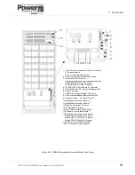
5. Close the maintenance bypass switch IA1 (in all cabinets in a multi-cabinet system).
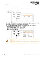
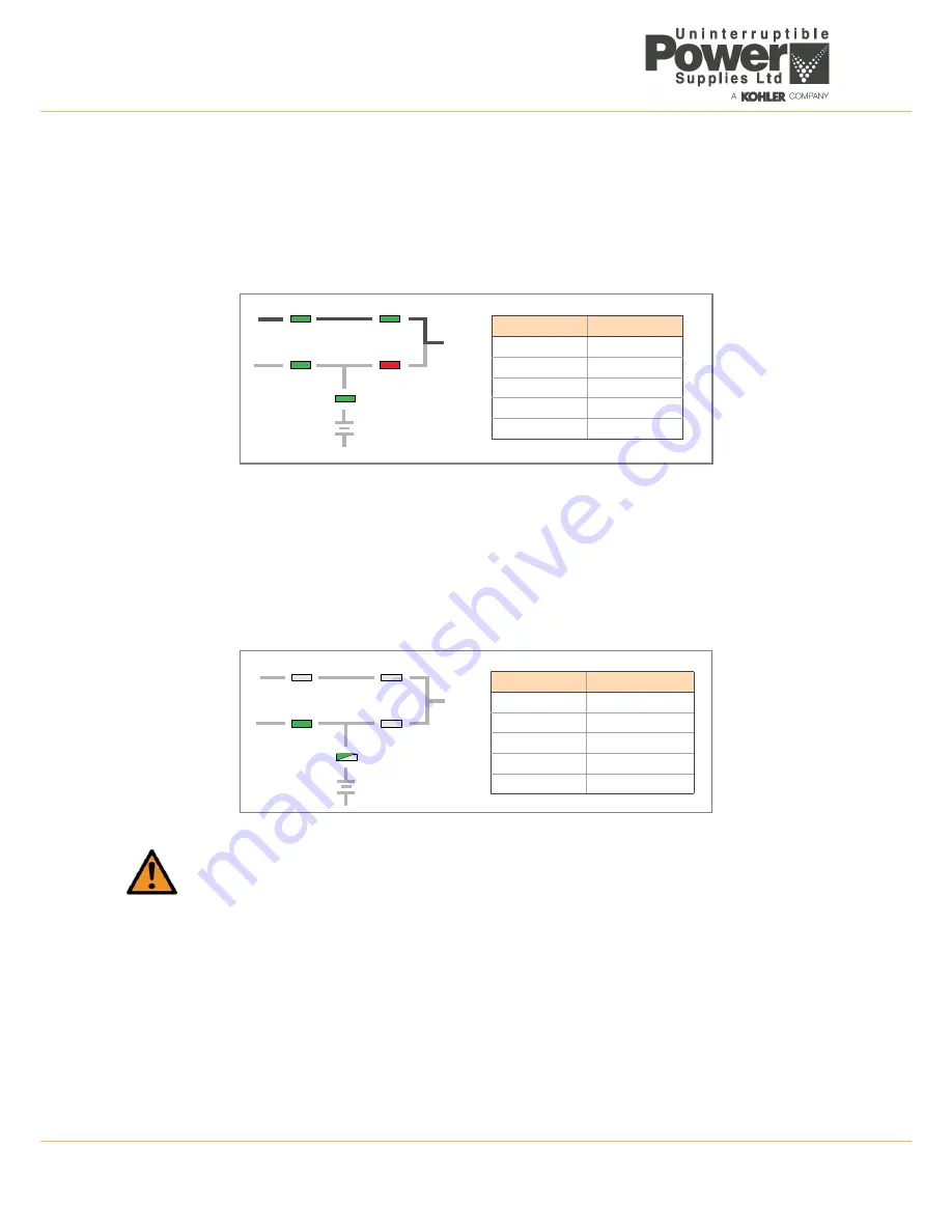
6. On all UPS modules check and confirm that:
a) The
INVERTER
LED has turned to red.
b) The
BYPASS
LED is green.
c) The LCD displays
MANUAL BYP IS CLOSED
.
Powering down a UPS module:
When the load is connected to the maintenance bypass supply, as described above, the UPS module(s) can be powered
down (for example, if required for maintenance/testing) using the following procedure:
Note:
Carry out the following procedure on each module in a parallel system to totally shut down the system.
7. On the UPS control panel simultaneously press both
ON/OFF
buttons.
a) The LCD panel will indicate:
LOAD OFF, SUPPLY FAILURE
.
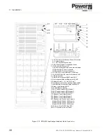
8. Open the fused battery isolator(s) associated with the module.
9. Open the module’s parallel isolator (IA2).
10. Open the bypass line fuse holder F2.
WARNING:
The UPS cabinet is still live at its input and output power terminals due to the closure of
maintenance bypass isolator.
WARNING:
Allow 10 minutes for the internal DC capacitors to discharge before touching any UPS internal
components.
WARNING:
The load is now supplied from the bypass mains and is not protected against power failure.
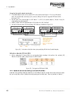
LINE 1
LINE 2
BY PASS
INVERTER
BATTERY
LOAD
LED
Colour
LINE 1
Green
LINE 2
Green
BY PASS
Green
INVERTER
RED
BATTERY
Green
LINE 1
LINE 2
BY PASS
INVERTER
BATTERY
LOAD
LED
Colour
LINE 1
Green
LINE 2
Off
BY PASS
Off
INVERTER
Off
BATTERY
Green Flashing


