UPS471-02-00 PW9000DPA User Manual UK Dated 06/08/14
53
4: Operation
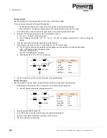
4.5.1 Removing a module
1. Verify that the load is on
BYPASS
and is supplied by the mains power on ALL UPS modules.
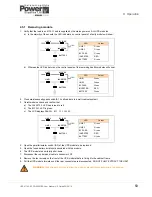
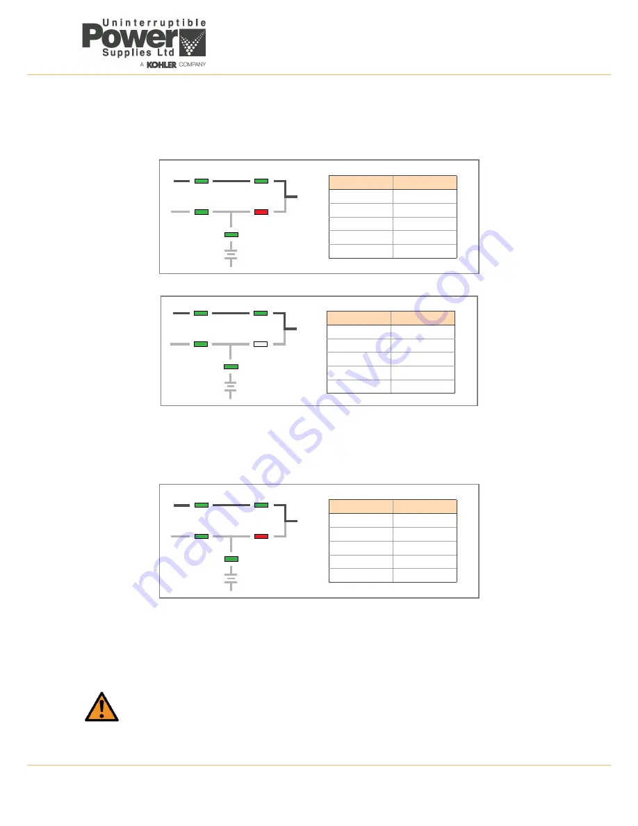
a) In the majority of the events the LED indicators on control panel of a faulty module will show:
b) Whereas the LED indicators on the control panels of the remaining healthy modules will show:
2. Close maintenance bypass switch IA1 (in all cabinets in a multi-cabinet system)
3. On
all
modules check and confirm that:
a) The
INVERTER
LED has turned to red.
b) The
BYPASS
LED is green.
c) The LCD displays
MANUAL BYP IS CLOSED
.
4. Open the parallel isolator switch (IA2) of the UPS module to be replaced.
5. Open the fused battery isolator(s) associated with the module.
6. The UPS module is now totally shut-down.
7. Disconnect the control panel cable to connector JD7.
8. Remove the four screws on the front of the UPS module that are fixing it to the cabinet frame.
9. Pull the UPS module forwards until the rear connectors are disconnected. DO NOT FULLY EXTRACT THE UNIT.
WARNING:
Wait at least 2 minutes to allow the module’s electrolytic capacitors time to discharge.
LED
Colour
LINE 1
Green
LINE 2
Green
BY PASS
Green
INVERTER
RED
BATTERY
Green
LINE 1
LINE 2
BY PASS
INVERTER
BATTERY
LOAD
LED
Colour
LINE 1
Green
LINE 2
Green
BY PASS
Green
INVERTER
RED
BATTERY
Green
LINE 1
LINE 2
BY PASS
INVERTER
BATTERY
LOAD
LED
Colour
LINE 1
Green
LINE 2
Green
BY PASS
Green
INVERTER
RED
BATTERY
Green
LINE 1
LINE 2
BY PASS
INVERTER
BATTERY
LOAD

