UPS471-02-00 PW9000DPA User Manual UK Dated 06/08/14
59
7: Options
7.1
Introduction
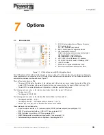
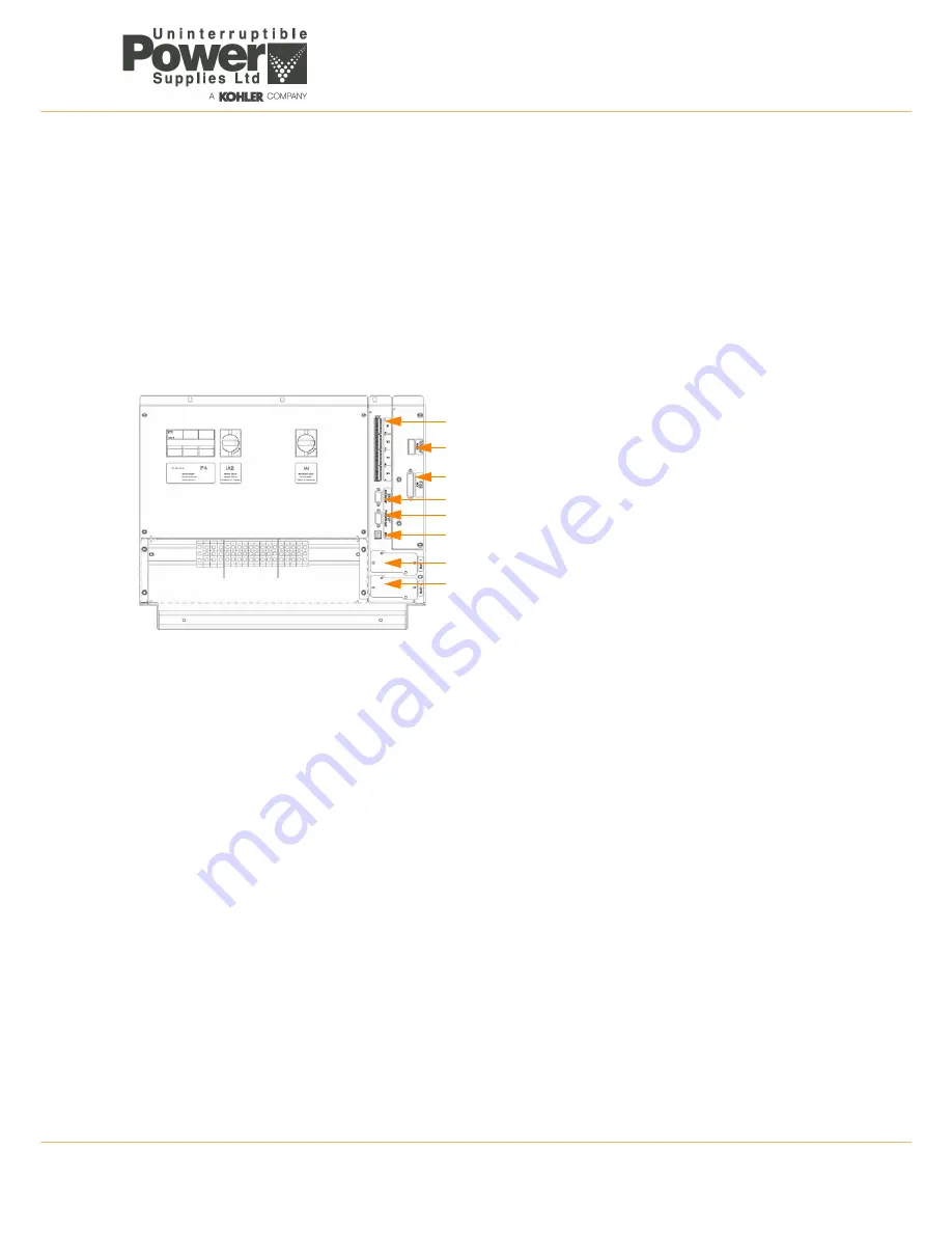
Figure 7.1 UPS Interface board (DPA-50 details shown)
Each UPS cabinet is fitted with an interface board, as shown in Figure 7.1, which enables various external monitoring and
control applications to be connected to the UPS system to satisfy particular site requirements. The interface board’s input
and output connections are shown above in Figure 7.1
The interface board has two LEDs:
• The green LED indicates the status of the interface and blinks twice per second when the board is fitted to the
‘master’ UPS (1st cabinet in the parallel system), and once per second when the board is fitted to a ‘slave’ UPS.
• The red LED is an alarm indication and illuminates to indicate a possible faulty board.
The following ports are active on the interface board when fitted to the ‘master’ UPS cabinet:
• The Input ports (X1)
• The Output port (X2, X3, X4)
The following ports are active on the Interface Board when fitted to a Slave cabinet:
• The Output ports X3/6 … X3/10
• The Output ports X4/1 …X4/10 (Means Alarm. Module 1, 2, 3,4, 5)
• All other input or output ports on the Slave boards are not activated
These interfaces are described below.
• Dry port customer interface – X1 (customer inputs), X2-X4 (customer outputs)
(see paragraph 7.2)
• RS232 Computer serial interface – USB & JD11
(see paragraph 7.3)
• RS232 Interface for multidrop – JD12
(see paragraph 7.4)
• SNMP/ Modem slots for remote monitoring/control –
(see paragraph 7.5)
• Cabinet paralleling connection and configuration –
(see paragraph 3.9)
7
Options
1
1. X1-X4 Customer interface on Phoenix Terminals:
X1 Customer Inputs
X2…X4 = Potential free contacts
2. SW1-9 Multi-Cabinet Configuration Switch
3. JD8 Parallel BUS connector
Only for paralleling cabinets use optional adapter:
JD5 Parallel BUS - Input Connector
JD6 Parallel BUS - Output Connector
4. JD11 RS232 / Sub D9/ female, PC interface
5. JD12 RS232/ Sub D9 / male for Multidrop ONLY
6. USB PC Interface
7. SNMP Slot for optional SNMP card ONLY
8. Slot for optional Modem/Ethernet card ONLY
2
3
4
5
6
7
8

