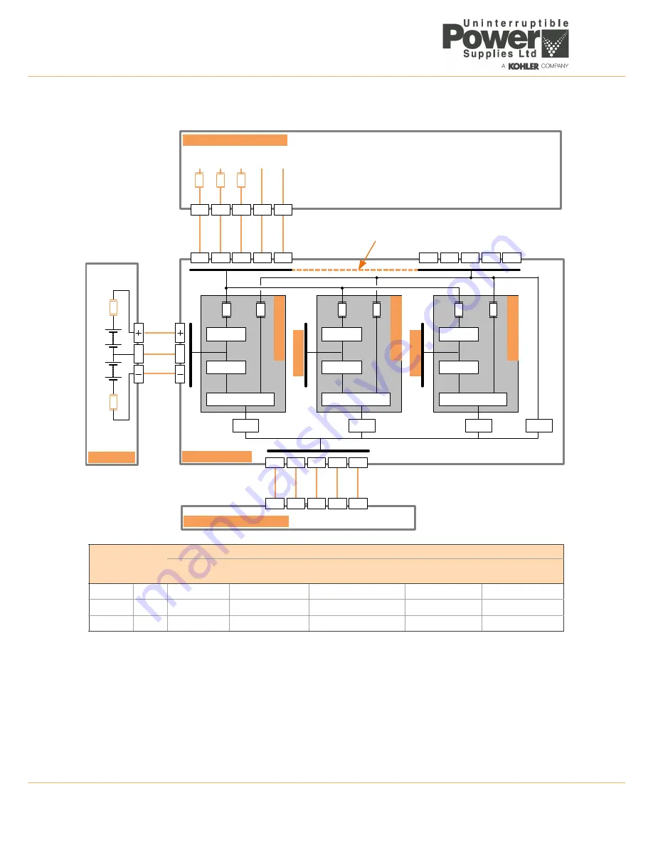
8: Specifications
72
UPS471-02-00 PW9000DPA User Manual UK Dated 06/08/14
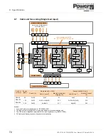
8.7
Cable and fuse sizing (Single feed input)
Notes:
1. Fuse and Cable recommendations to IEC 60950-1:2001
2. The fuse and cable rating details in the above tables are a recommendation only.
3. The UPS must be installed to prescribed IEC or local regulations (e.g. BS7671:2008).
4. DC Cables and Battery fuses are bespoke to the installation.
Cabinet
(Frame)
Power
(kVA)
Single Input (3 x 400V)
Output (3x400V, 0.8 pf)
Fuse A (A)
Cable A (mm
2
)
Max Input with batt
charging (A)
Cable D (mm
2
)
Nominal Current
(A)
DPA-50
50
3x100
5x25
67
5x25
72
DPA-150
150
3x250
5x120 or 5x(2x50)
202
5x120 or 5x(2x50)
218
DPA-250
250
3x400
5x(2x95)
337
5x(2x95)
362
Cable
E
Fu
se
E
Rectifier
Inverter
Static
Switch
IA
2
Fu
se
A
Ca
bl
e
D
Ca
bl
e
A
Mains
Supply
(3x380/400/415)
IA
1
F1
F2
Maint.
Bypass
3L3
3N
PE
3L1
3L2
L3
N
PE
L1
L2
PW9000
CABINET
MAINS
DISTRIBUTION
BOARD
UPS
MAINS
SUPPLY
BATTERY
1
N
N
LOAD
DISTRIBUTION
BOARD
L3
N
PE
L1
L2
St
at
ic
Byp
as
s
Li
n
e
Rectifier
Inverter
Static
Switch
IA
2
F1
F2
St
at
ic
Byp
as
s
Li
n
e
Rectifier
Inverter
Static
Switch
IA
2
F1
F2
St
at
ic
Byp
as
s
Li
n
e
Po
w
er
Mo
d
ul
e
1
Po
w
er
Mo
d
ul
e
2
Po
w
er
Mo
d
ul
e
3
B
A
TTE
RY
2
B
A
TTE
RY
3
1L3
1N
PE
1L1
1L2
2L3
2N
PE
2L1
2L2
INPUT/
BYPASS
LINKS
FITTED
1L1
– 2L1,
1L2
– 2L2,
1L3
– 2L3,
1N
– 2N

