4
2. Hardware Description
The following information is provided to give the user an understanding of how to connect the
TRP-C37M to the LAN and serial device. A review of the switch settings and the functionality of
the LED’s are also provided.
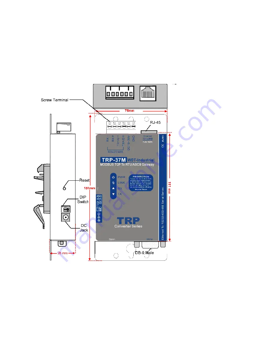
2-1. Panel layout
2-2. LED indicator
PWR LED
: System is ready.(Blinking)
LINK LED:
Ethernet cable connection and data active.
TX/RX LED
: UART Transiting/Receiving Indicator.
Summary of Contents for TRP-C37M
Page 6: ...6 2 6 DB 9 Pin male pin assignment ...
Page 9: ...9 b WEB Server ...
Page 10: ...10 c Serial Console ...
Page 34: ...34 ...
Page 35: ...35 7 Application1 ...


