background image

From the library of: Superior Sewing Machine & Supply LLC

Summary of Contents for 36200 Series

Page 1: ...6200AB 6200AK 6200AX ATALOG No 118L THIRD EDITION C 0 L U M B I A CLASS 36200 HIGH SPEED CYLINDER FLATSEAMER MACHI ES INDUSTRIAL SEWING MACHINES UNION SPECIAL CORPORATION CHICAGO From the library of Superior Sewing Machine Supply LLC ...

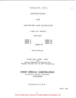
Page 2: ...6200 X STYLES 36200 AX Third Edition 36200 AA 36200 AB 36200 AK Copyright 1960 1962 By Union Special Corporation Rights Reserved in All Countries UNION SPECIAL CORPORATION INDUSTRIAL SEWING MACHINES CHICAGO Printed in U S A 2 March 1981 From the library of Superior Sewing Machine Supply LLC ...
Page 3: ...t the 36211 Retainer 17 EXPLODED VIEWS AND DESCRIPTION OF PARTS Drive Unit Belt Guard and Mounting Stud 18 Reference Number Part Number and Description 19 Main Frame Miscellaneous Covers Bushings and Take up 20 Reference Number Part Number and Description 21 Needle Lever Main Shaft Crankshaft and Miscellaneous Oiling 22 Reference Number Part Number and Description 23 Foot L erand Tension Parts 24 ...

Page 4: ...um weight mater ial where seaming and closing elastic is not necessary Seam Specification 607 FSa 1 36200 X TAPE SEAMER Five threads for joining and taping fronts of knit briefs in gne operation Seam Specification 607 LS 4 Mod 36200 AA Same as Style 36200 A except prepared for Pedestal Installation 36200 AB Same as Style 36200 B except prepared for Pedestal Installation 36200 AK Same as Style 3620...

Page 5: ... right thread 1 It will be noted inthe above example that the eccentric and bearing are not listed The reason is that replacement of these parts individually is not recommended so the complete sub assembly should be ordered In those cases where a part is common to all of the machines covered by this catalog no specific usage will be mentioned inthe description However when the parts for the variou...

Page 6: ... filled at the caps H and J Oil capacity of Class 36200 is 2 ounces in bottom oil reservoir and 2 5 ounces in the top reservoir Use a straight mineral oil Saybolt viscosity of 90 to 125 seconds at 100o Fahrenheit The level is checked at the two sight gauges K and L located on the right side of the main frame under the foot lifter lever and at the front of the cylinder respectively Maintain oil lev...

Page 7: ...7 AA cc THREADING AND OILING DIAGRAM FOR STYLES 36200 A B From the library of Superior Sewing Machine Supply LLC ...

Page 8: ...From the library of Superior Sewing Machine Supply LLC ...
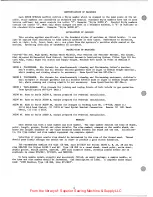
Page 9: ...dent upon the conditions of the operation Since the Handwheel Pulley which is grooved for a 1 1 or 3L section Vee Belt has a pitch diameter of 2 1 4 inches the size of the Motor Pulley may be approximated by the following formula 2 25 x R P M of Machine Pitch Dia of Motor Pulley R P M of Motor For Union Special Electro Drive Pulleys add 1 4 inch to the calculated pitch diameter to obtain the outsi...

Page 10: ...perative to hold the free ends of all the threads firmly behind the Foot before starting the machine until a small amount of chain is formed This is termed starting the chain Machine will then chain indefinitely REPLACING THE NEEDLE Union Special Needles for the FLATSEAMER are made with two flats on front of Shank This design auto matically assists operator in correctly locating the relative posit...

Page 11: ... not aligned improperly If the Stitch Tongue and Throat Plate are properly seated and the Needle position is not correct it is probable that the Cylinder has been forced out of position It is therefore necessary to realign the Cylinder as outlined on Page 12 When the Needles are in correct position to the Throat Plate the space at the left of the Needle in the slot of the Stitch Tongue is 006 inch...

Page 12: ...n does not represent synchronization and Looper timing cannot be accomplished there Synchronization occurs only when Needle Bar has risen 156 5 32 inch At this height the Looper point should appear at the same relative position to the Needles whether rotation is effected clockwise or counterclockwise Synchronization is easily and accurately obtained by use of Gauge 21227 CG Page 43 Fig D INSTRUCTI...

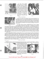
Page 13: ...n looper gauge which is 084 inch Fig E If conditions are not met adjustment is obtained by removing Cylinder Side Cover I l6286 Page 35 and loosening Looper Avoid Link Ball Joint Stud right in 1129478 Di 1 Page 31 to raise or lower Ball Joint Raising Ball Joint shortens avoid motion and lowering lengthens avoid motion Reposition gauge and repeat preceeding method Normal Looper gauge is 3 16 inch W...

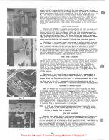
Page 14: ...OOT ADJUSTMENT To assemble Presser Foot to machine raise Needle Bar to its highest position and remove Retainer While foot is slipped under Needles swing the Upper Knife into opening and engage the Cover Thread Carrier and Hook Driving Segment 36251 L Page 37 with Hook Driving Sleeve 36251 B Page 33 The Presser Bar may now be passed thru the Segment and into the Presser Foot Shank Tighten Presser ...

Page 15: ... A allowing about 1 8 inch clearance between Guide and lower Bearing of Knife Driving Arm To obtain the best trimming condition between Lower Knife A Fig L 1 and Upper Knife B Fig L 1 the distance between Knife Drive Connection Ball Joint Left 52848 B Page 33 and Knife Drive Connection Ball Joint Right 52848 C Page 33 should be set so that when the Upper Knife is at the left end of its travel the ...

Page 16: ...itch loops The Take up should be timed to cast off during the interval between the crossing of the thread by th Cover Thread Hook and the start of rise of the Needle Bar The t off should always occur prior to Needle Bar rise Otherwise tension will remain in the Gover Thread and the fonnation of the first needle thread loop will be impaired The tension of the Gover Thread is approximately 1 oz meas...

Page 17: ...hten Set Screws of Oil Pump Driven Gear CAUTION Do not compress the Oil Seal Ring enough so that the Pump Shaft is hard to turn as it will damage the Driving Gear 35897 BY on the Mainshaft Torque should be set at 2 to 4 ounces inch 8 Replace the two Idle Gears 51493 E and put on the Housing Covers 36297 A and 36297 J Do not use any sealer between the Housing and Covers Just be sure the surfaces ar...

Page 18: ... 2 1 I I l l J L1 From the library of Superior Sewing Machine Supply LLC ...

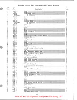
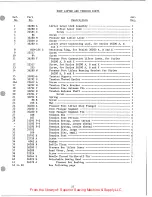
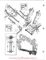
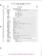
Page 19: ...S 36200 A B AND X DRIVE UNIT BELT GUARD AND MOUNTING STUD Description Nut Washer Neoprene Isolator Felt Isolator Mounting Stud Vee Belt 21 inch outside circumference Auxiliary Support and Drive Screw Oil Gauge Screw Ball Bearing Cap Gasket Amt 6 6 6 9 3 1 1 2 1 6 2 2 Screw 4 Ball Bearing 2 Collar Screw Bushing Machine Support Gear Locating Pin Oil Filler Plug Gear Shaft Screw Handwheel Assembly Pu...

Page 20: ...20 From the library of Superior Sewing Machine Supply LLC ...
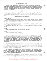
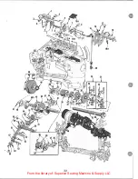
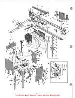
Page 21: ...p Cover front Oil Sight Gauge Oil Cup Screw Plug Screw Gasket Nut Nut Spring Middle Cover Hinge Screw Screw Presser Foot Lifter Stop Plunger Bushing Oil Gauge Float Oil Height Indicator Oil Sight Gauge Washer Screw Gasket Oil Drain Screw Oil Shield Oil Wick Bushing Housing Gasket Bushing Housing includes bushing Screw Plug Screw Needle Lever Shaft Bushing rear Oil Wick Needle Lever Shaft Bushing f...

Page 22: ...22 From the library of Superior Sewing Machine Supply LLC ...

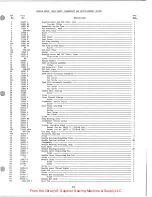
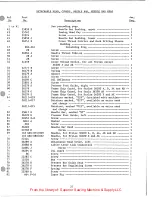
Page 23: ... 4 Gear Shaft 1 Vent Screw 2 Oil Pump Housing 1 Gasket 1 Oil Pump Driven Gear 1 Screw 2 Oil Seal Ring 1 Washer 1 Housing Cover and Oil Tubes front 1 Plug Screw 1 Screw 2 Spacer Washer 1 Take up Shield Assembly 1 Gasket 1 Oil Reservoir front 1 Oil Seal Ring 2 In take Filter 1 Feed Drive Eccentric Assembly 1 Screw 2 Set Screw 1 Set Screw 1 Feed Lift Eccentric Assembly 1 Screw 2 Set Screw 1 Set Screw...

Page 24: ... 24 I i 16A I I I 0 From the library of Superior Sewing Machine Supply LLC ...

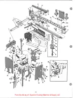
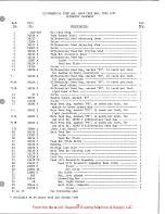
Page 25: ... A B and X 1 Screw 2 Screw 2 Presser Foot Connection Lifter Lever for Styles 36200 A B and X 1 Screw for Styles 36200 A B and X 1 Screw for Styles 36200 A B and X 1 Presser Foot Lifter Bearing Bracket for Styles 36200 A B and X 1 Tensiou Support 1 Tension Thread Eyelet 3 Screw 6 Tension Plate Bracket 2 Tension Disc Release Pin 7 Tension Release Shaft 1 Screw 1 Spring 1 Screw 1 Nut 1 Presser Foot L...

Page 26: ...12 26 I I 16A I I I 0 7 From the library of Superior Sewing Machine Supply LLC ...
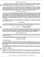
Page 27: ...ining Ring 1 Screw 2 Needle Thread Take up 1 Screw 4 Screw 1 Cover Thread Eyelet for all Styles except 36200 X and AX 1 Screw 1 Spring 1 Washer 1 Screw 1 Oil Deflector 1 Screw 1 Presser Foot Guide right 1 Frame Chip Guard for Styles 36200 A B AA and AB 1 Frame Chip Guard for Style 36200 AK 1 Frame Chip Guard for Styles 36200 X and AX 1 Retainer marked 029 furnished with machine 1 Retainer marked 0...

Page 28: ...8 From the library of Superior Sewing Machine Supply LLC ...
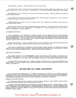
Page 29: ...vy operations 1 Differential Feed Dog marked PB 16 teeth per inch for light operations 1 Differential Feed Dog marked PF 14 teeth per inch left hand offset 1 Differential Feed Dog marked FN 14 teeth per inch right hand offset 1 Screw 1 Needle Guard marked FZ 1 Screw 1 Main Feed Dog marked PK 14 teeth per inch for medium to heavy operations 1 Main Feed Dog marked PL 16 teeth per inch for light oper...

Page 30: ...m 41 43 37 30 From the library of Superior Sewing Machine Supply LLC ...
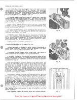
Page 31: ...receding page Feed Drive Assembly 1 Feed Drive Eccentric Assembly 1 Screw 2 Set Screw 1 Set Screw 1 Nut left thread 1 Connecting Rod 1 Nut right thread 1 Ball Joint 1 Screw 2 Ball Fork 1 Screw 1 Screw 2 Screw 1 Oil Seal Ring 1 Bushing 1 Differential Driving Link Stud 1 Differential Feed Driving Link Slide Block 1 Feed Rocker 1 Link Pin 1 Driving Link Screw 1 Bushing 1 Feed Rocker Driving Link 1 Nu...

Page 32: ...32 From the library of Superior Sewing Machine Supply LLC ...

Page 33: ...Cover Thread Carrier and Hook Driving Sleeve I Knife Driving Bracket I Bushing 1 Screw 2 Knife Holder Guide Plate 1 Bushing 1 Roll Pin 2 Nut l Knife Drive Connection Ball Joint left I Screw 2 Nut 1 Cover Thread Carrier and Hook Driving Connecting Rod Ball Joint 1 Screw 2 Presser Bar Guide 1 Screw I Nut I Nut I Knife Drive Connection Ball Joint right 1 Screw 2 Washer 1 Knife Drive Lever 1 Oil Seal ...

Page 34: ...34 From the library of Superior Sewing Machine Supply LLC ...
Page 35: ...1 Screw 1 Screw 1 Stop Screw 2 Nut 2 Adjusting Plate 1 Gasket 1 Adjusting Lever 1 Oil Seal Ring 1 Spring Hasher 1 Fiber Washer 1 Looper Shaft Bushing rear 1 Looper Thread Guide Wire 1 Screw 1 Pin 1 Cylinder Hinged Cover 1 Screw 1 Screw Pin 1 Chain Cutting Knife 1 Chain Cutting Knife Guard 1 Screw 1 Screw 1 Cylinder Hinged Spring Support Stud 1 Spring 1 Screw 1 Dowel Pin 2 Throat Plate Stitch Tongu...

Page 36: ...36 From the library of Superior Sewing Machine Supply LLC ...

Page 37: ...d A 1 Screw 1 Spring 1 Chip Guard 1 Screw 1 Stationary Knife Clamp 326 inch 8 28 mm Bright Finish 1 Stationary Knife Clamp 318 inch 8 08 mm Black Fi nish 1 Screw 2 Presser Foot Shoe right for No 36220 A presser foot See Page 39 Presser Foot Shoe right for No 36220 presser foot See Page 39 Presser Foot Shoe left for No 36220 A presser foot See Page 39 Presser Foot Shoe left for No 36220 presser foo...

Page 38: ...J 5 12 9 7 11 16 18 15 13 38 From the library of Superior Sewing Machine Supply LLC ...

Page 39: ...h 4 rnm thick 11 32 inch 8 7 rnm wide short toe Used on 36220 A 1 Presser Foot Shoe right 1 64 inch 4 rnm thick 11 32 inch 8 7 mm wide short toe for heavyweight material Used on 36220 A 1 Presser Foot Shoe left 1 64 inch 4 mm thick 11 32 inch 8 7 mm wide extended toe for heavyweight material Used on 36220 A 1 Presser Foot Shoe right 1 64 inch 4 rnm thick 11 32 inch 8 7 rnm wide extended toe for he...

Page 40: ...40 From the library of Superior Sewing Machine Supply LLC ...
Page 41: ...ad Stand Rod for Styles 36200 A B and X 1 Spool Seat Support for Styles 36200 A B and X 1 Screw 2 Thread Stand Base for Styles 36200 A B and X 1 Screw 1 Cap Plug 1 Pad for Styles 36200 A B and X 6 Spool Pin for Styles 36200 A B and X 6 Nut for Styles 36200 A B and X 12 Spool Seat Disc for Styles 36200 A B and X 6 Washer for Styles 36200 A B and X 6 Socket with 7 32 inch hexagon bit for aligning cy...

Page 42: ...42 From the library of Superior Sewing Machine Supply LLC ...

Page 43: ...Needle Setting Block 1 Nut 1 Thumbscrew 1 Synchronizing Gauge Rod 1 Looper Clamp and Height Gauge 1 Screw 1 Screw 1 Wrench for 3 16 inch square nut on No 35851 K 1 Torque Rod for Styles 36200 AA AB AK and AX 1 Kit of Gauges includes Nos 21227 BV 21227 CG 21227 CN 1 Looper Travel Gauge includes Nos 21227 CM 21227 CS 1 Looper Travel Gauge Pointer 1 Looper Travel Gauge Plate 1 Looper Alignment Gauge ...

Page 44: ...EAD STAND FOR PEDESTAL INSTALLATION 0 0 111 1 H G 660 181 2110 1 B 2 1 21114 AK 6 21114 AG 6 21114 660 340 660 181 660 339 ror Style 36200 AK only 44 From the library of Superior Sewing Machine Supply LLC ...

Page 45: ...J lJRit L TAP HOLE TH S S LJE OF TREALJU AS SHOWN N YIEW A OF 477 H 7 TAP IJif ILL 201 j 20 H 3 THf I I W A PL 511 THIS PLANOCRAPII SHOWS THE METHOLJ FOR CONt E i T NG TilE 4001 PELJEST4L TO JSE 25480lJZ TR 4 JL NT 1 LOCK HECIIANISM KIT From the library of Superior Sewing Machine Supply LLC ...

Page 46: ...7 CJ 43 21227 CK 43 21227 CM 43 46 Part No Page 21227 CN 43 21227 cs 43 21227 CT 43 21227 cu 43 21227 cv 43 21233 E 44 21233 AJ 44 21261 M 210 19 43 21371 UE 19 21388Y 41 21388 AW 41 21388 AX 41 21388 AY 43 21661 43 21661 D 43 21662 Y 43 21662 z 43 21662 AA 43 21663 43 21663 E 43 21665 43 21705 19 21756 G 23 22504 c 29 22513 27 22516 A 21 22517 25 22519 F 23 22524 25127 22528 29 22539 M 21 22539 N...

Page 47: ...B 33 36251 c 33 36251 D 27 36251 E 37 36251 F 37 36251 G 37 36251 H 37 36251 K 35 37 36251 L 37 36251 M 23 47 Part No Page No 36251 N 23 36251 P 33 36251 u 37 36253 A 33 36253 B 33 36253 G 33 36253 H 33 36253 J 33 36256 21 36256 A 21 36256 B 35 36260 21 36261 33 36261 A 23 36263 23 36264 A 27 36264 B 25 36264 D 23 36270 33 36271 21 36271 A 21 36271 D 21 36271 E 21 36271 F 21 36273 A 33 36273 c 33 ...

Page 48: ...s promptly and efficiently Whatever your loca tion there is a Union Special Representative to serve you Check with him today ATLANTA GA MONTREAL CANADA BOSTON MASS TORONTO CANADA CHICAGO ILL BRUSSELS BELGIUM DALLAS TEXAS LEICESTER ENGLAND LOS ANGELES CAL LONDON ENGLAND NEW YORK N Y PARIS FRANCE PHILADELPHIA PA STUnGART GERMANY Representatives and distributors In all Important Industrial cities thr...

Reviews: