REPLACING THE TAPE CUTTER KNIVES
Swing-off the end cover.
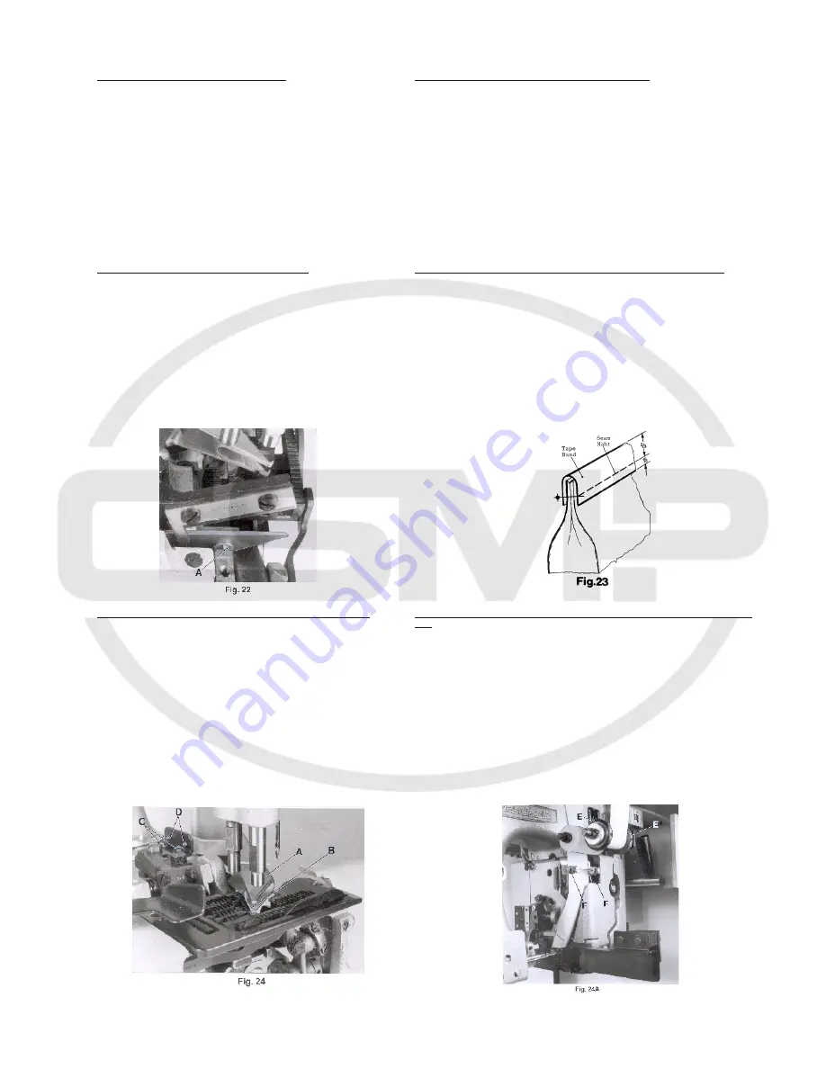
Remove the presser foot for replacing the upper knife on
styles 80800U, UA, UL and UAL and for replacing the lower
knife, additionally the throat plate.
The upper knife on styles 80800TL and TAL can be
replaced directly. For replacing the lower knife remove
both presser foot parts, the throat plate and the cloth
plate and loosen the cutter plate.
Make sure, especially when mounting resharpened
knives, that the cutting edges overlap approx. 0.3 mm
(.012") in cutting position. Recheck the shear angle, if
necessary.
Swing-in end cover and remount the parts removed.
TAPE FOLDER FOR STYLES 80800U AND UL
Take out the tape folder with fastening parts from the
machine accessories and assemble it as shown on page
50. The folder has to be aligned with the support rods to
the top surface of throat plate. The height should be
adjusted so, that the tape fully covers the bag opening
and the seam is located in the lower third of the tape
(see Fig. 23).
The folder can be adjusted for tape widths from 50 to 70
mm (1 31/32 to 2 3/4"). Set the guides so, that the bag
opening will be equally bound.
Assemble the tape reel as shown on page 50.
ADHESIVE TAPE FOLDER FOR STYLES 80800TL AND TAL
The adhesive tape folder (A, Fig. 24) has to be assembled
so, that it fits close to the bevelling of the cut-out in the
throat plate (see Dig. 24). The inner lower edge of the
folder mouth (B) must be flush with the top surface of
throat plate, and set as far to the left in the throat plate
cut-out so the adhesive tape will fully cover the closed
bag opening. The folder bracket and the folder can be
set accordingly after loosening screws (C and D, Fig. 24)
Retighten screws.
Assemble the tape reel as shown on page 50.
Assemble the guide rollers for the adhesive tape and the
bag guide rail as shown on page 52. Set the collars (E,
Fig. 24A) on the front guide roller and the collars (F) on
the folder to the width of the used adhesive tape. Insert
the adhesive tape as shown in Fig. 24A.
19
AUSTAUSCH DER BANDABSCHNEIDER-MESSER
Klappen Sie das Abschlußblech weg.
Bei den Maschinen 80800U, UA UL und UAL muß zum Austausch
des Obermessers der Drückerfuß und zum Austausch des Unter-
messers zusätzlich die Stichplatte entfernt werden.
Bei den Maschinen 80800TLund TAL kann das Obermesser direkt
ausgewechselt werden. Zum Austausch des Untermessers bau-
en Sie die beiden Drückerfußteile, die Stichplatte und die Stoff-
platte aus und lösen die Abschneiderplatte.
Beachten Sie, insbesondere bei nachgeschliffenen Messern, daß
sich die Messerschneiden in Schneidstellung etwa 0,3 mm über-
lappen müssen. Überprüfen Sie, wenn notwendig, den Scher-
winkel.
Schwenken Sie das Abschlußblech zurück und montieren Sie die
ausgebauten Teile wieder.
BANDEINFASSAPPARAT FÜR DIE MASCHINEN 80800U UND UL
Nehmen Sie den Bandeinfaßapparat mit Befestigungsteilen aus
dem Zubehör der Maschine und montieren Sie ihn wie auf Seite
50 gezeigt. Der Apparat wird mit den Trägerbolzen zur Stich-
plattenoberfläche ausgerichtet. Die Höhe muß so eingestellt
werden, daß das Einfaßband die Sacköffnung voll umschließt und
die Naht etwa im unteren Drittel des Bandes liegt (siehe Fig. 23).
Der Apparat kann für Bandbreiten von 50 bis 70 mm eingestellt
werden. Stellen Sie die Führungen so, daß die Sacköffnung gleich-
mäßig eingefaßt wird.
Montieren Sie den Bandrollenhalter, wie auf Seite 50 gezeigt.
KLEBEBAND-EINFASSAPPARAT FÜR DIE MASCHINEN 80800TL UND
TAL
Der Klebeband-Einfaßapparat (A, Fig. 24) muß so montiert sein,
daß er satt an der Schräge des Ausschnitts in der Stichplatte an-
liegt (siehe Fig. 24). Die innere untere Kante des Apparate-Mund-
stücks (B) muß mit der Stichplattenoberfläche eben sein und so-
weit nach links in den Stichplattenausschnitt gestellt werden, daß
das Klebeband die zugenähte Sacköffnung voll umschließt. Der
Apparatehalter und der Apparat können nach Lösen der Schrau-
ben (C und D, Fig. 24) entsprechend eingestellt werden. Ziehen
Sie die Schrauben wieder an.
Montieren Sie den Bandrollenhalter wie auf Seite 50 gezeigt.
Montieren Sie die Führungsrollen für das Klebeand und die Sack-
Leitschiene wie auf Seite 52 gezeigt. Stellen Sie die Stellringe (E,
Fig. 24A) auf der vorderen Führungsrolle und die Stellringe (F) am
Apparat auf die Breite des verwendeten Klebebandes ein. Le-
gen Sie das Klebeband wie in Fig. 24A gezeigt ein.
www.college-sewing.co.uk
Summary of Contents for 80800R
Page 24: ...24 w w w c o l l e g e s e w i n g c o u k ...
Page 26: ...26 w w w c o l l e g e s e w i n g c o u k ...
Page 28: ...28 w w w c o l l e g e s e w i n g c o u k ...
Page 30: ...30 w w w c o l l e g e s e w i n g c o u k ...
Page 32: ...32 w w w c o l l e g e s e w i n g c o u k ...
Page 34: ...34 Loctite 262 CE66 w w w c o l l e g e s e w i n g c o u k ...
Page 36: ...36 w w w c o l l e g e s e w i n g c o u k ...
Page 38: ...38 w w w c o l l e g e s e w i n g c o u k ...
Page 40: ...40 w w w c o l l e g e s e w i n g c o u k ...
Page 42: ...42 w w w c o l l e g e s e w i n g c o u k ...
Page 44: ...44 w w w c o l l e g e s e w i n g c o u k ...
Page 46: ...46 w w w c o l l e g e s e w i n g c o u k ...
Page 48: ...48 w w w c o l l e g e s e w i n g c o u k ...
Page 50: ...50 w w w c o l l e g e s e w i n g c o u k ...
Page 52: ...52 w w w c o l l e g e s e w i n g c o u k ...
Page 54: ...54 w w w c o l l e g e s e w i n g c o u k ...
Page 59: ...59 NOTES NOTIZEN w w w c o l l e g e s e w i n g c o u k ...


