26
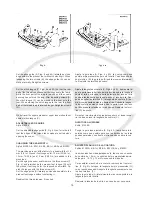
In the extreme left upper end position of upper looper (A,
Fig. 11 B), the distance between the left edge of looper eye
and the center of needle (N) should be 6 mm (15/64 in.)
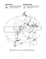
If an adjustment is necessary, loosen nuts (L and R, Fig.
12) and turn connecting rod (C) forward or backward as
required to obtain the required position.
NOTE: The left nut (L) has a left hand thread. Temporarily
snug the two nuts (L and R) manually.
Rotate handwheel in operating direction until the upper looper
is in its extreme right lower end position. The upper looper
with thread hook should not contact any machine parts during
its motion.
If required loosen clamp screw (D, Fig. 12) in the drive lever
(E) and set the lever so that the upper looper (F) clears at
all points. Retighten clamp screw (D).
After this setting recheck the position of the spreader to the
needle, as described above. Reset with connecting rod (C,
Fig. 12) if required and tighten nuts (L and R).
Rotate handwheel in operating direction. On the upward
travel of upper looper (B, Fig. 13 B) its tip (C) must pass as
close as possible in the recess behind the eye of the lower
looper (A) without contacting it.
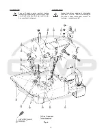
If an adjustment is required, loosen nut (G, Fig. 7) on the
double joint and swing the looper lever with lower looper
accordingly to the right or left. Retighten nut (G.)
NOTE:
Check the setting of the needle bar height after
making this adjustment and reset if required.
Refer to paragraph
SETTING THE HEIGHT OF
THE NEEDLE BAR.
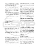
SETTING THE THREAD RETAINER
Styles 81500A, B, B1H, B2, BA, BA1H, BA2 and 81500C
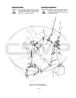
The thread retainer (B, Fig. 14) should retain the lower looper
thread before the lower looper (A) enters into the needle
thread loop.
Viewed from the left end of the machine the thread retainer
(B) should pass as close as possible on the left side of lower
looper (A) when swinging upward without contacting it.
On the most upward travel of its swing motion the tip of the
thread retainer (B) should be as close as possible below the
underside of the throat plate. It should not contact neither
the throat plate nor the feed dog.
After loosening screw (C, Fig. 14) the thread retainer (B)
can be moved to the left or right. Retighten screw on the flat
of the thread retainer shank.
After loosening the two set screws (D), shaft (E) with the
thread retainer (B) can be rotated into the correct position.
Make sure to remove all lateral end play when tightening
the set screws.
En la posición izquierda superior extrema del looper supe-
rior (A, Fig. 11 B), la distancia entre el costado izquierdo del
ojo del looper y el centro de la aguja (N) debería ser de 6
mm.
Si un ajuste es necesario, suelte las tuercas (L y R, Fig. 12)
y gire la varilla de conexión (C) hacia adelante o hacia atrás,
como sea necesario, hasta obtener la posición requerida.
NOTA: La tuerca izquierda (L) enrosca a la izquierda. Tem-
poralmente acomode las dos tuercas (L y R) ma-
nualmente.
Gire el volante en dirección de operación hasta que el looper
superior esté en su posición derecha extrema inferior. E l
looper superior y el gancho del hilo no deben tocar ninguna
parte de la máquina durante este movimiento.
De ser necesario, suelte el tornillo de sujeción (D, Fig. 12)
en la palanca de movimiento (E) y ajústela de manera tal
que el looper superior (F) no toque ninguna otra pieza. Re-
ajuste el tornillo de sujeción (D).
Después de realizar este ajuste, verifique la posición del
spreader superior con la aguja, tal y como se describe en el
párrafo anterior. Reajuste con la barra de conexión (C, Fig.
12) de ser necesario y apriete de nuevo las tuercas (L y R) .
Gire el volante en dirección de operación. En la extrema
superior de su recorrido, la punta (C) del looper superior
(B, Fig. 13) debería pasar lo mas cerca posible del espacio
detrás del ojo del looper inferior (A) pero sin tocarlo.
Si un ajuste es necesario, suelte la tuerca (G, Fig. 7) en la
unión doble y mueva la palanca del looper con el looper
inferior adecuadamente hacia la derecha o izquierda. Apriete
la tuerca (G.)
NOTA:
Revise la altura de la barra de aguja después de
realizar estos ajustes y reajuste de ser necesa-
rio. Refiérase al párrafo
AJUSTE DE LA ALTU-
RA DE LA BARRA DE AGUJA
.
AJUSTE DEL RETENEDOR DE HILO
Estilos 81500A, B, B1H, B2, BA, BA1H, BA2 y 81500C.
El retenedor de hilo (B, Fig. 14) debe retener el hilo del
looper inferior antes de que el looper inferior (A) entre en el
lazo del hilo de la aguja.
Visto desde la extrema izquierda del final de la máquina el
retenedor de hilo (B) debe pasar tan cerca como sea posi-
ble del lado izquierdo del looper inferior (A) en su movi-
miento hacia arriba, pero sin tocarlo.
En su posición mas alta de este movimiento, la punta del
retenedor del hilo (B) debe pasar tan cerca como sea posi-
ble por debajo de la parte inferior de la plancha de aguja.
No debe tocar ni la plancha de aguja ni el diente alimenta-
dor.
Después de soltar el tornillo (C, Fig. 14) el retenedor de hilo
(B) debe poder moverse hacia la izquierda o hacia la dere-
cha. Reajuste el tornillo en la parte plana del tronco del
retenedor de hilo.
Después de soltar los tornillos de sujeción (D), el tronco
(E) con el retenedor de hilo (B) puede moverse hasta lograr
la posición correcta. Asegúrese de corregir cualquier movi-
miento fuera de sitio antes de apretar los tornillos.
Summary of Contents for 81500B2
Page 8: ...8 INSTALLATION INSTALACION...
Page 10: ...10...
Page 21: ...21...
Page 23: ...23 Fig 10 Fig 11 Fig 11 A Fig 11 B Fig 11 C Fig 12...
Page 25: ...25...
Page 28: ...28...
Page 33: ...33 VIEWS AND DESCRIPTION OF PARTS VISTAS Y DESCRIPCIONES DE LAS PARTES Y PIEZAS...
Page 34: ...34...
Page 36: ...36...
Page 38: ...38...
Page 40: ...40...
Page 42: ...42...
Page 44: ...44...
Page 46: ...46...
Page 48: ...48...
Page 50: ...50...
Page 52: ...52...
Page 54: ...54...
Page 56: ...56...
Page 58: ...58...
Page 60: ...60...
Page 62: ...62...
Page 64: ...64...
Page 68: ......

