background image

29

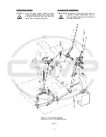
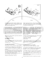
For setting the upper feed dog with respect to the slot ends
in the presser foot and the tooth spaces of the lower feed
dog, loosen screw (D, Fig. 18) and turn drive lever (E)
accordingly to the front or rear. Retighten screw.

For setting the small gap between the feed dogs loosen
nut (F, Fig. 20). Turning in screw (G) increases the gap,
turning it out decreases the gap. Retighten nut (F).
For matching the upper feed dog travel with the lower feed
dog travel loosen screw (A, Fig. 21). Moving the ball link in
the slot of rocker lever (B) to the front decreases the upper
feed dog travel, moving it to the rear increases the travel.
Retighten screw (A).

HINT: In general the travels of lower and upper feed dog

are set equally. Depending on the fabric to be sewn
however, it may be necessary to set a slightly longer
upper feed dog travel in order to get a proper end
matching of the fabric plies.

Also refer to paragraph 

CHANGING STITCH LENGTH.

UPPER FEED DOG MOTION

Style 81500A

On this style the upper feed dog does not lift on its return
travel. It works as a swinging upper feed, moving parallel
to the height of the presser foot.

UPPER FEED

Standard on


Styles 81500B, B1H, B2, BA, BA1H, BA2,

81500C and 81500E

SETTING THE MOTION OF THE UPPER FEED DOG

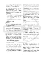
On the return travel, the upper feed dog should lift so high
that no fabric will be pulled against the sewing direction.
The motion should be set so that the rear four teeth of the
upper feed dog (B, Fig. 19) remain approx. 1/3 of their
height in the presser foot slots when lifting.

For adjustment loosen the two screws (H, Fig. 19) and
raise the supporting yoke (J) when the upper feed dog
should lift more or lower it when it should lift less. Retighten
screws (H).

On request an alternating upper feed is available.

PRESSER FOOT PRESSURE

Rotate handwheel until the lower feed dog is below the
throat plate. Loosen knurled nut (A, Fig. 22) and turn out
T-screw (B) until it does not exert any pressure on the leaf
springs. In this position, the pressure exerted on the presser
foot should be so strong that the presser foot bottom and
the front end of the presser foot tongue rest squarely on
the throat plate.
By relocating the collars (C, Fig. 23) which serve as a leaf
spring rest, on the left and right presser bar, the pressure
can be changed. Raising the collars increases the pressure,
lowering the collars decreases it.

Para ajustar el diente alimentador superior con respecto a los
extremos de las ranuras en el pie prensatelas y los espacios
entre los dientes del diente alimentador inferior, hay que sol-
tar  el tornillo  (D, Fig. 18) y girar la palanca de accionamiento
(E) hacia adelante o atrás respectivamente.  Apriete de nuevo
el tornillo.
Para ajustar la pequeña brecha dentro del diente transporta-
dor, suelte la tuerca (F, Fig. 20). Girando el  tornillo (G) hacia
adentro aumenta la brecha, hacia afuera la disminuye. Ase-
gure la tuerca (F) de nuevo.
Para ajustar el movimiento del diente superior con el diente
inferior, suelte el tornillo  (A, Fig. 21). Moviendo la junta esfé-
rica en la ranura de la palanca de accionamiento (B) hacia el
frente disminuye el movimiento del diente alimentador supe-
rior, moviéndolo hacia atrás lo incrementa.  Apriete de nuevo
el tornillo (A).
DATO:


Generalmente, los movimientos de ambos dientes

están ajustados igual.   Dependiendo del tipo de tejido a co-
ser, sin embargo, puede ser necesario ajustar un poco  mas
largo el movimiento del diente superior para poder tener   un
acabado parejo en las laminas de material.
Refiérase también al párrafo  

AJUSTE  DEL  LARGO DE LA

PUNTADA.

MOVIMIENTO DEL DIENTE ALIMENTADOR SUPERIOR

Estilo 81500A

En ésta máquina el diente alimentador superior no  se eleva
en su recorrido de regreso. Se balancea moviéndose parale-
lamente a la altura del pie prensatelas

DIENTE SUPERIOR

Normal en los estilos 81500B, B1H, B2, BA, BA1H, BA2,
81500C y 81500E

AJUSTE DEL MOVIMIENTO DEL DIENTE ALIMENTADOR
SUPERIOR

En su movimiento de regreso, el diente alimentador superior
debería moverse tan alto que ningún material sea arrastrado
contra la dirección de costura. El movimiento debe ser ajus-
tado de manera tal que los últimos 4 dientes traseros del diente
alimentador superior  (B, Fig. 19) mantengan aproximada-
mente 1/3 de su altura de las ranuras del pie prensatelas
cuando se levanta.
Para ajuste, suelte los dos tornillos  (H, Fig. 19) y levante el
soporte (J)  cuando el diente alimentador superior deba subir
mas, o bájelo cuando deba bajar menos. Asegure los torni-
llos  (H).
Bajo pedido un diente alimentador superior alternando tam-
bién esta disponible.

PRESION DEL PIE PRENSATELAS

Gire el volante hasta que el transporte inferior se encuentre
debajo de la plancha de la aguja. Afloje la tuerca (A, Fig. 22)
y afloje el tornillo (B) hasta que no haga más presión contra
los muelles. En esta posición la presión al pie prensatela
debería ser tal que la planta del pie prensatela y la parte
delantera de la lengüeta del pie prensatela se apoyen plano
en la plancha de la aguja.
Regulando los anillos (C, Fig. 23) en la barra derecha e
izquierda del pie prensatela, que sirven como soporte para
los muelles, se puede variar la presión. Subiendo los anillos
aumenta la presión, bajándolos disminuye la presión.

Summary of Contents for 81500B2

Page 1: ...CATALOGO DE PARTES Y PIEZAS MANUAL NO CATALOGO NR G234 FOR STYLES PARA ESTILOS 81500A B B1H B2 BA BA1H BA2 C E MIRAKLES SINGLE NEEDLE SINGLE TWO OR THREE THREAD OVERSEAMING MACHINES MIRAKLES MAQUINA O...

Page 2: ...dos de repuestos Este manual explica detalladamente los ajustes para la operaci n de la m quina Las ilustraciones sirven para demostrar los ajustes y las letras en referencia indican los puntos espec...

Page 3: ...ON DEL LOOPER UPPER AND LOWER FEED DRIVE MECHANISM MECANISMOS DEL TRANSPORTE SUPERIOR E INFERIOR PRESSER BARS PRESSER BAR SPRINGS AND PRESSER FOOT LIFTER LEVER BARRAS DEL PIE PRENSATELA MUELLES PARA L...

Page 4: ...que se confirme que la unidad de coser esta conforme con el reglamento del Directivo de las M quinas de la Comunidad Europea 98 37 EC Anexo II B La m quina solamente se puede utilizar para su uso pre...

Page 5: ...heck the direction of rotation Breakage may occur when the direction of rotation is wrong 9 Maintenance repair and conversion work see item 8 must be done only by trained technicians ors p e c i a l s...

Page 6: ...de costura 12 mm hasta 21 mm Ancho de costura 10 mm hasta 22 mm Aguja normal recomendada 9859G430 172 Rango de puntada 6 a 13 mm Ajuste de fabrica 10 mm Di metro efectivo del volante 150 mm Velocidad...

Page 7: ...operaci n recomendada81dB A Peso neto 37 kg 81500B1H Igual a la 81500B pero con cortador electroneu m tico caliente de cadeneta y pie prensatelas y levantador del diente superior activados electroneum...

Page 8: ...8 INSTALLATION INSTALACION...

Page 9: ...or pulley see Fig 2 Remount motor belt guard INSTALACION Continuaci n 1 Desempaque la m quina y los accesorios 2 Monte la placa de base A Fig 1 con los 4 tornillos tuercas y arandelas B en los huecos...

Page 10: ...10...

Page 11: ...tion has to be changed the reversing of the polarity is only allowed to be done by a skilled electrician 11 Enganche la cadena a la palanca levantadora de la m quina de coser y al peque o pedal en la...

Page 12: ...ricating When using clutch motors with or without actuation lock wait until motor has completely stopped LUBRICACION Antes de lubricar apague el interruptor principal Con un motor de embrague sin fren...

Page 13: ...eva m quina por la primera vez hay que fijar y ajustar el engrasador cuentagotas Lubrique todos los puntos indicados en el diagrama de lubricaci n Fig 4 Llene el engrasador cuentagotas hasta la mitad...

Page 14: ...de enhebrar Cuando utilice motor con clu tch debe esperar hasta que el mismo se detenga totalmente THREADING DIAGRAM CAUTION Turn off main power switch before threading When using clutch motors with o...

Page 15: ...de enhebrar Cuando utilice motor con clu tch debe esperar hasta que el mismo se detenga totalmente THREADING DIAGRAM CAUTION Turn off main power switch before threading When using clutch motors with o...

Page 16: ...ilice motor con clu tch debe esperar hasta que el mismo se detenga totalmente Para enhebrar estilos 81500A B B1H B2 BA BA1H BA2 y 81500E por favor vea diagrama en Fig 5 Para enhebrar estilo 81500C por...

Page 17: ...0E see Fig 6 A ALIMENTACION DEL HILO DE LA AGUJA Generalmente el rodillo del alimentador del hilo de la aguja B Figs 5 y 5A que est situado en la parte delantera izquierda del brazo debajo de la tapa...

Page 18: ...ad tension if required Ajuste la gu a tope A Figs 6 y 6A tan cerca como sea posible al pie prensatelas pero sin tocarlo Cuando suelte los dos tornillos B la gu a tope A podr moverse lateralmen te Reaj...

Page 19: ...TING MANTENIMIENTO PRECAUCION Antes de efectuar cualquier trabajo de mantenimiento apague el interruptor principal de la m quina Con un motor de embrague sin freno espere hasta que el motor se detenga...

Page 20: ...S PARA MECANICOS Preste atenci n a las REGLAS DE SEGURI DAD mientras realiza ajustes Antes de realizar ajustes en la m quina quite la tapa frontal y el protector de dedos el diente alimentador superio...

Page 21: ...21...

Page 22: ...DE LA ALTURA DE LA BARRA DE AGUJA Gire el volante en direcci n de operaci n hasta que la pun ta del looper inferior A Fig 9 o la punta del spreader infe rior A Fig 9 A sobresalga 3 mm en los estilos 8...

Page 23: ...23 Fig 10 Fig 11 Fig 11 A Fig 11 B Fig 11 C Fig 12...

Page 24: ...hasta que el spreader superior est en su posici n extrema inferior El spreader superior no debe tocar ninguna parte de la m qui na durante esta operaci n Si es necesario afloje el tornillo de sujeci n...

Page 25: ...25...

Page 26: ...ierdo del ojo del looper y el centro de la aguja N deber a ser de 6 mm Si un ajuste es necesario suelte las tuercas L y R Fig 12 y gire la varilla de conexi n C hacia adelante o hacia atr s como sea n...

Page 27: ...centrado lateralmente en las ranuras de la plancha de aguja B De ser necesario alg n ajuste suelte Ios dos tornillos de sujeci n C y mueva el eje oscilante D a la izquierda o derecha como sea requeri...

Page 28: ...28...

Page 29: ...re los dientes del diente alimentador inferior hay que sol tar el tornillo D Fig 18 y girar la palanca de accionamiento E hacia adelante o atr s respectivamente Apriete de nuevo el tornillo Para ajust...

Page 30: ...elevaci n del pie prensatelas se limita con el anillo de ajuste D Fig 23 en la parte superior de la barra derecha del pie prensa tela Cuando la aguja est en su posici n m s baja y el pie prensa tela...

Page 31: ...an ser apretadas lo m ximo posible si no se indica de otra manera Especificaciones especiales de los torques para barras de conexi n junturas tornillos etc se encuentran en las ilustraciones de las pa...

Page 32: ...YLE OF MACHINE FOR WHICH PART IS ORDERED PEDIDO DE PIEZAS DE REPUESTOS Este cat logo fue dise ado para facilitar los pedidos de los repuestos Los dibujos de grupos espec ficos del mecanismo demuestran...

Page 33: ...33 VIEWS AND DESCRIPTION OF PARTS VISTAS Y DESCRIPCIONES DE LAS PARTES Y PIEZAS...

Page 34: ...34...

Page 35: ...te Grooved Drive Pin Spring Valve Oiler Spring Valve Oiler Felt Rayon Wool Bocina de la barra del pie prensatelas Bocina de la barra de aguja Distribuidor de aceite Tornillo de punto fijo sin cabeza T...

Page 36: ...36...

Page 37: ...t for cloth plate Screw Base Plate Roll Pin Screw with nut and washer T Screw for sewing machine Pin Protector de la barra de aguja Cubierta del brazo Tornillo T Tuerca estriada Cubierta frontal Torni...

Page 38: ...38...

Page 39: ...e up Roller Set Screw Roller Stud Assembly Set Screw Spring Spring Ball Roller Stud Set Screw Looper Thread Guide for 81500A B BA C Screw Poste de la tensi n para 81500A B BA 81500C 81500E Distanciado...

Page 40: ...40...

Page 41: ...B BA Eyelet for looper threads for 81500C Set Screw Looper Thread Guide for 81500A B BA Looper Thread Guide for 81500C Set Screw Looper Thread Guide Stud Spacer for lower looper thread tension post f...

Page 42: ...42...

Page 43: ...66LA 80650LA 22587 80656 80636A G22515A 80630C 80630 80630G 80630D PI18 80652 22587 81322A HA66K 80885 80621A 81321B 80 80674 80 80643 A9469N 22574 Barra de la aguja Manguito Anillo de metal para 8150...

Page 44: ...44...

Page 45: ...ntrica de accionamiento del looper y spreader superior Conj Exc ntrica accionamiento looper inferior Conexi n Tornillo insertable Mecha para el aceite Pasador de la mecha para el aceite Exc ntrica Tor...

Page 46: ...46...

Page 47: ...d Lift Eccentric Spot Screw headless Feed Drive Eccentric Assembly Connecting Link Screw Oil Wick Oil Wick Bushing Eccentric Spot Screw headless Stud Washer Nut Roll Pin Eje impulsor Palanca del impul...

Page 48: ...48...

Page 49: ...pring Guide Plate Screw Collar Screw Collar Set Screw Leaf Spring upper Leaf Spring lower Spring Rest Shank Screw Presser Bar left for 81500A B BA C E Presser Bar left for 81500B1H B2 BA1H BA2 Presser...

Page 50: ...50...

Page 51: ...crew Coupling PA Tube 6 x 1 length 1 5 m Speed Regulating Coupling Cable with plug 37 pins for 997A735 not shown Cable with plug 37 pins for 997A852 not shown Presser Bar left for 81500B1H B2 BA1H BA2...

Page 52: ...52...

Page 53: ...cortador caliente de cadeneta Tubo PA 6x4 Largo 1 m Cable para 997A735 Cable para 997A852 Enchufe de acople V lvula del solenoide Tornillo Tornillo Soporte Interruptor de rodilla V lvula de reducci n...

Page 54: ...54...

Page 55: ...PNEUMATIC HOT THREAD CHAIN CUTTER 81500B1H BA1H CONTROL PARA EL SISTEMA ELECTRO NEUMATICO CORTADOR CALIENTE DE CADENETA PARA 81500B1H BA1H 1 2 Control Box of hot thread chain cutter 999 315B Control...

Page 56: ...56...

Page 57: ...cket Mikro Valve Screw Cloth Plate Roller Lever Lever Screw Lock Washer Screw Washer Shim Ring Washer Pipe Clamp not shown Coupling not shown Coupling not shown Cortador caliente electroneum tico Cort...

Page 58: ...58...

Page 59: ...nco del looper para 81500C Gancho del hilo marcado GP Tornillo Tornillo de sujeci n Retenedor de hilo marcado GR Tornillo Guarda agujas posterior Tornillo con cabeza hexagonal Soporte de la plancha de...

Page 60: ...60...

Page 61: ...le Guard Screw Needle Guard front Screw Diente alimentador superior Tornillo Pie prensatelas Tornillo Leng eta del prensatelas marcada WL 19 Tornillo Leng eta de costura Tornillo Gu a lateral Gu a lat...

Page 62: ...62...

Page 63: ...mm Porta conos 1 hilo para 81500E Porta conos 2 hilos Porta conos 3 hilos Base Varilla del portaconos Gu a para los hilos Arandela aisladora de 16 mm Arandela aisladora de 12 mm Arandela Pasador del...

Page 64: ...64...

Page 65: ...ne Fastening Screw Locking Ring Clamp Spring Oil Drain Reservoir Wrench size 9 32 7 2 mm Wrench size 7 32 5 5 mm Wrench size 3 8 and 1 2 9 5 and 12 7 mm Socket Head Wrench size 1 8 3 2 mm Tweezers Scr...

Page 66: ...1C25 51 671G22 51 671G23 51 69H 47 59 61 74A 45 74F 45 59 61 78057 59 61 79 43 80 43 80233 47 80236 45 80280A 37 80293A 35 80437A 37 80438 37 80440 37 80463A 65 80566 43 80620H 43 80621A 43 80630 43 8...

Page 67: ...7X 47 98 45 99240 45 59 61 99241 59 61 99373G 51 99376A 49 995 735QH 51 53 995 852FH 51 53 99590J 51 53 99623A 41 99681J 63 65 99681JA 63 65 99683C 51 99683M 51 99711LH 37 57 99711LHA 37 99711MH 57 99...

Page 68: ......

Reviews: