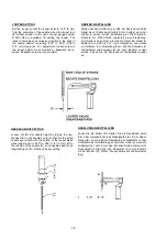
TRANSPORTEUR-EINSTELLUNG
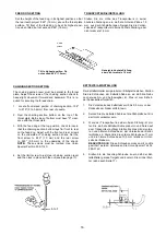
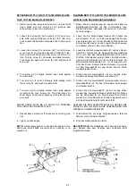
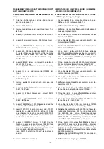
Stellen Sie die Höhe des Transporteurs in seiner
höchsten Stellung so ein, daß die hinteren Zähne 1,5
mm aus der Stichplatte ragen. Neigen Sie die Vorder-
seite des Transporteurs in seine höchste Stellung, aber
nicht mehr als 1,5 mm.
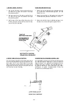
KETTELTEIL-EINSTELLUNG
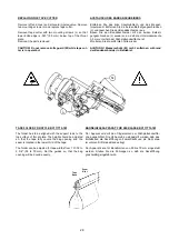
Der Kettelteil-Halter soll parallel zur Stichplatte stehen. Stellen
Sie die Schrauben der Kettelteil-Nabe so ein, daß die Nabe
noch etwas hin- und herbewegbar ist. Dies ist zum Sichern
der Fadenkette erforderlich.
1. Die Vorderseite des Kettelteils soll 5 bis 5,5 mm von der
Rückseite der Nadel entfernt sein.
2. Setzen Sie die Kettelteil-Sohle auf die Stichplatte auf. Sie
darf nicht verkantet sein.
3. Wenn der Transporteur in seiner oberen Stellung ist, prü-
fen Sie, daß die Kettelteil-Sohle plan vorn und hinten auf
dem Transporteur aufliegt. Stellen Sie dies mit der vorde-
ren und hinteren Schraube an der Unterseite der Kettel-
teil-Nabe ein. Stellen Sie die vordere Schraube auf 1 mm
und die hintere Schraube auf 0,5 mm relativ zur Unter-
seite der Nabe ein.
BEACHTEN SIE:
Diese Schrauben müssen mit Loctite
gesichert werden. Verwenden Sie Union Special Teil Nr.
999-114C.
4. Stellen Sie die Anschlag-Schraube so ein, daß der Ket-
telteilhalter gerade freigeht und kontern Sie mit der Mut-
ter (siehe auch Seite 17).
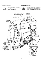
Geneigt in höchste Stellung,
aber nicht mehr als 1,5 mm
Tilt to highest position. Do
not exceed .060" (1.5 mm
)
16
CHAINING SECTION SETTING
The chaining section lever must be parallel to the throat
plate. Adjust the screws of the chaining section shank to
have slight movement forward and backward. This is re-
quired for securing the thread chain.
1.
Locate front raised portion of chaining section .196"
to .216" (5 to 5.5 mm) from rear of needle.
2. Rest the chaining section bottom on the top of the
throat plate. Both sides of bottom must have "0" clear-
ance with the throat plate.
3. With the feed dog at the top position, check to insure
that the chaining section bottom lays flat front to rear
on the feed dog. Adjust with the front and rear screws
on the underside of chaining section shank. Set the
front screw to .040" (1.0 mm) and the rear screw
to .020" (0.5 mm) to the underside of the shank.
NOTE:
These screws must be loctited. Use Union
Special Part No. 999-114C.
4. Set the limit screw to just clear chaining section lever
and then lock in place with the nut (see also page 17).
FEED DOG SETTING
Set the height of the feed dog in its highest position so that
the rear teeth project .060" (1.5 mm) above the throat plate
surface. Tilt front of the feed dog to be at its highest posi-
tion when tilted, but not exceed .060" (1.5 mm).
Summary of Contents for BC100
Page 15: ...13...
Page 25: ...23...
Page 44: ...42 19 Needle Looper Synchronisation 19 Nadel Greifersynchronisierung...
Page 49: ...47 NOTES NOTIZEN...
Page 50: ......


