


| 23
C64.65201 Issue 3
Jun 2019
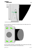
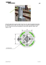
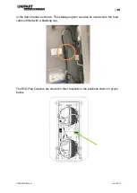
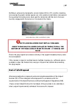
The diagram above shows highlighted in green, that the vertical adjustment slot in
the side bracket has been replaced with a simple through hole bolt securing the
housing to the base plate and the E-Clip/Locking Plate on the pivot bar with a split
pin arrangement.
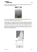
Alignment is carried out by fitting the detachable scope to the ALT and then all
vertical/horizontal adjustment is facilitated at the baseplate.
This method means the ALT can be aligned without the head and post being
present, which offers greater flexibility to the customer in terms of installation
planning.
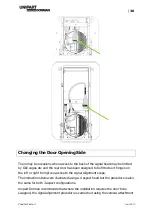
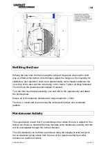
Backboard Arrangement
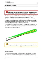
The signals are required to display a uniform backboard of at least 300mm from the
centre of the lit aspect and the following procedure is applicable to both mounting
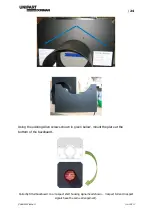
arrangements. To prevent damage to the lower portion of backboard during transit a
removable section is fitted in a stowed position to enable the signal head to be
bolted securely to its pallet. As part of the installation, this extension piece must be
moved into its operational position below the aperture once it has been removed
from the pallet.
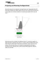
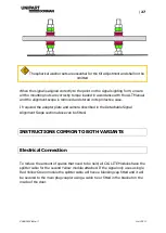
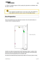
The backboard must be moved to its in-service position before aligning the
signal as in the transit position; it obscures the holes in the backboard the scope
looks through and the signal will not meet the 300mm backboard criterion
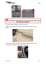
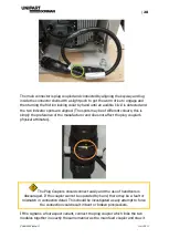
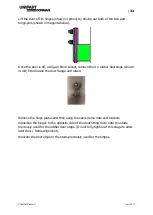
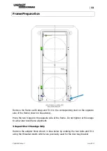
Remove the Lower Backboard Extension from its stowage position above the
aperture by removing the two 3mm Allen screws shown in blue below. Refit the two
screws and dispose of the 2 white plastic labels and the black plastic edge protector
properly.


