Instruction Manual
40
80
Optical flame fire detector FD 8040 is designed to provide early warning of a fire condition responding to open
flame. The fire detector reacts within the light spectrum of the flame and has maximum sensitivity of the
infrared range. The opearation principle is based on the reception of flame emissions with their typical flicker
frequency within the whole spectrum range. The infrared sensor signal - amplified, filtered and shaped is
being sent to the time delay circuit. If the flame impact has decreased during the time delay , the fire detector
dos not activate.
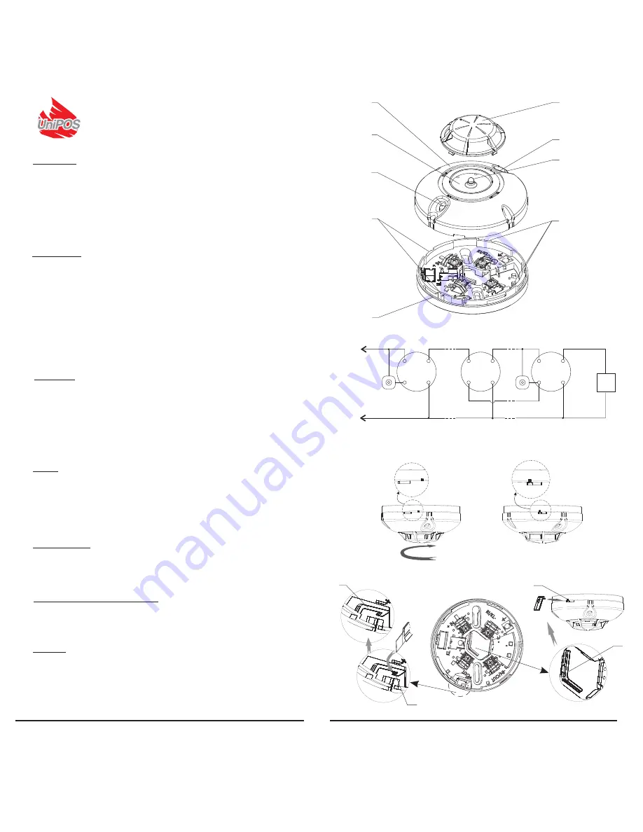
The fire detector consists of (fig.1) printed board, mounted in a plastic body with optical filter and bottom side.
The flat point pivot
screw (optional) prevents the fire detector of unauthorized removal. A 2 mm tip
screwdriver is required for locking and unlocking. The two red LEDs of the fire detector (fig.1) are indicating
Fire condition, providing 360 angle visibility. It is recommended that the fire detectors are mounted in
premises, where a possible development of fire condition is supplemented by flame. Avoid mountong in
premises with flickering lights. The fire detectors shall be mounted on the ceiling in a way, that do not alow
explosure to direct sunlight.
INTRODUCTION
Supply voltage
(from12- to30)V DC
Current consumption in Duty Mode
300 μA
Current consumption in Fire condition
- with a base type 8000 & 8000D
8mA/12V DC;- 25mA/ 30V DC
-
with a base type 8000R & 8000DR
18mA/12V DC;- 55mA/ 30V DC
Sensitivity
in accordance with EN54-10, class 2 (IR)
Time delay
T-10s ( optional T-5s;T-20s)
Protected area
Angle of visibility 45o
Type of the line connection
two-wire
Degree of protection
IP 40
Operation Temperature Range
from Minus 10 C to 55 C
o
o
Relative humidity resistance
C
(92±3)% at 40
o
Dimensions (base type 8000 included)
100mm h 47 mm
Ø
Output in Alarm condition
Terminal RI/KL for RI31 or RI31S
Cross section of the connection wire
(0.8-1.5mm2)
TECHNICAL DATA
Fire detector FD8040 is to be used with base types 8000 (standard base), 8000D (with schottky diode),
8000R ( with relay output ), 8000 DR (with schottky diode and resistor 500) or 8000L (with resistor 510)
When mounting the fire detector and the base observe the following sequence :
Fix the base to the ceiling of the protected premise using fixing screws and wood screws.
Complete the electrical wiring as shown on (fig 2.), and according to the rational design of the premise.
Fix the fire detector to the base by means of bayonet joint (fig1,pos1). When fixing, make sure that the
bench mark of the detector stands about 20 mm before the respective bench mark of the base so that the
plastic channels fully coincide (fig1,pos2), then rotate clockwise to complete location (fig3,pos1). The
bench marks should fully coincide (fig3,pos2).
Lock the detector (fig4.) head to the base by screwing the flat pivot point screw, using a specialized
screwdriver in clockwise direction to complete location, ensure not to over tighten. Unlock by unscrewing
(pos.4) the flat pivot point screw until the detector's head is released from the base.
INSTALLATION
TESTING
The fire detector shall be tested after installation, as a part of the Fire Alarm System of the premise or
after performing service schedule , in the following sequence :
1.Power supply the fire detector from the fire alarm line,to which it is mounted. The supply voltage value
is given in section Technical data of the instruction manual herein. Supply voltage can be provided by the
Fire alarm panel or by an auxiliary source 24V DC/0,1A.
2.Use a tester for flame detectors after a minute. In 30 seconds the LEDs shall be illuminated (Fire
condition).
3.Cut off the power supply of the detector for a while about 2 seconds or reset the fire panel . It should
remain in duty mode and ready for new activation after 30 seconds.
SERVICE SCHEDULE
1. Inspection for visible physical damages weekly
2. Satisfactory Operation test weekly
3. Check and clean dust contaminations every 6 months
*
* Remove the detector from the base , than remove the chamber from the detector (fig1pos6.)You can
use for a cover a cleaning materials, washing and drying.The optical chamber and the photodiod you
have to clean with clean cloth .
PACKING, STORAGE AND TRANSPORTATION
1. Each device is to be placed in separate package, together with the instruction manual.
2. The flame detectors should be stored packaged in dry store premises аt temperature from 0 to 35 C
o
o
and relative humidity resistance up to 85% in non-aggressive environment, microorganisms or vibrations.
Shelf life -10 years.
3.The fire detectors should be transported in transport packing, observing the transportation markings on
the boxes.
WARRANTY
The warrant period is 36 months from the date of purchase.
The manufacturer guarantees the normal operation of the fire detector providing that the requirements of
the instruction manual herein have been observed.
The manufacturer does not bear warranty liabilities for damages caused through accidental
mechanical damage, misuse, adaptation or modification after production. The manufacturer bears
warranty liabilities for damages in the fire detector caused through manufacturer's fault only.
OPTICAL FLAME FIRE DETECTOR
FD 8040
fig.3.1
fig.4
5
3
6
2
3
7
3
2
1
4
fig.1
1
2
fig.2
fig.3.2
FD 8040
FD 8040
RI 31-n
+
-
+OUT
+IN
-IN/OUT
RI/KL
-IN/OUT
RI/KL
FD 8040
-IN/OUT
RI/KL
RI 31-
1
L
L
+OUT
+IN
+OUT
+IN
4
EOL
Producer UniPOS Ltd
http://www.unipos-bg.com
:
.Bulgaria,5800 Pleven, San Stefano 47 Str.,
Producer UniPOS Ltd
http://www.unipos-bg.com
:
.Bulgaria,5800 Pleven, San Stefano 47 Str.,


