UniPOS
Wireless Fire Alarm Control Panel VIT 01
Instruction manual
Page 27
Revision 10/02.17
Pages 51
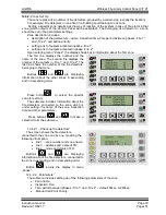
Test switching on/switching off of the outputs
can be done by the second element of the menu
for testing outputs.
The outputs are displayed by the following
order:
Monitor output 1;
Monitor output 2;
The outputs of the routers (controllers) in
ascending order of registration.
The last window of the test indicates the
condition of the following voltages in the Control
Panel:
For the normal operation of the system,
parameters must have the following parameters:
Monitored outputs 1 and 2
– 180 to 800;
Supply voltage 220V
– more than 150;
Output user supply 28V
– more than 450;
Ground
– 80 to 500;
Back up batteries supply
– more than 625;
If any of the parameters is not in the limits, the status filed on the first line displays the
corresponding index:
B
– back up batteries supply;
E
– ground;
H
– Monitor output 2 is shorted;
L
– Monitor output 2 interrupted;
h
– Monitor output 1 shorted;
l
– Monitor output 1 interrupted;
D
– Fault in the output supply 28V;
A
– Fault 220V supply.
12.4.1.1.2. ‘’Indication’’- this option will perform test of the local sound indication and all LEDs
supported by the Control Panel. On the display is shown the message ‘’TEST INDICATION!’’ and
all LEDs must be switched on except ‘’System fault’’ indicator. Duration of the test is about 15
seconds.
12.4.1.2. Menu
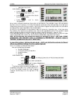
„Setting the clock”
The menu allows for setting the hour, minute,
weekday, month and a year.
By button
select the parameter for setting.
Buttons
and
are increasing or
decreasing the selected parameter.
Holding down button
completes the setting,
without the need to pass through all the settable
elements.
At the end of the setting, the seconds of the clock are reset and the new real time starts from the
beginning of the minute.
12.4.1.3
.
Menu
„Control Panel Parameters”
The submenu includes adjustment of the following parameters of the Control Panel:
Language ( chapter 12.4.1.3.1);


