Manufacturer
:
UniPOS Ltd.
,
47 San Stefano Street, Pleven 5800, Bulgaria,
http://www.unipos-bg.com
3. Installation
3.
1
.
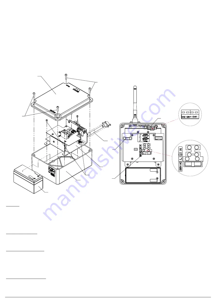
If necessary d
ismantle the cover (po
s
.7,
fig.
2) from the base (pos.5,
fig.
2) by developing the four screws (pos.1,
f
ig.2)
.
3.
2
.
Remove the
batter
y
(pos.6,
fig.
2) and remove the antenna (pos
.
2,
fig.2
).
3.3.
Dismantle the chassis (pos.3,
fig
.2) from the base (pos.5,
f
ig
.
2) by developing the four screws (
pos.4
,
f
ig
.
2).
3.4.
Four drilling holes in the bottom of the base (the exempt purpose for seats) for mounting to the wall.
3.5.
Based on drill hole to bring the mains power supply cables and
output
.
3.6.
The wires are passed inside the box. Basis (pos.5,
f
ig.2) is attached to the wall using appropriate fixings, keeping the place chosen in accordance
with the detailed design and the assessment of patency of the signal.
3.7.
The base (pos.5,
f
ig.2) is mounted chassis -
k
it (pos.3,
f
ig.2) by four screws (
pos.
4,
fig.
2)
3.8.
Remove the
fuse
(pos.1,
fig
.3) and join the wires of the mains power supply and
monitored
output (
pos.
2,
fig.
3) (where the
output
will be used).
When delivered, the controllable output terminals are terminated with 5.6kΩ resistor.
3.9.
Mount the antenna (pos.2, fig.2).
3.10.
Fit the battery (pos.6,
fig.
2) and join the wires to the terminals thereof. Red wire to (+) and to blue (-) battery.
3.11.
Place the fuse (pos.1,
f
ig.3). The device is powered from
power supply
.
3.12.
Mount the cover (po
s
.7,
f
ig.2) to the base (pos.5,
f
ig.2) by four screws (pos.1,
f
ig.2).
3.13.
C
hange the mode of
router
in
mode
"
Duty
"
(see Instruction Manual VIT 01).
Fig
.2
Fig
.3
TESTING
The
router
is to be tested after installation as a part of the Fire Alarm System of the premise or after service schedule in the following sequence:
1.
Check the activation of th
e
output by a command from the Control Panel – up to 5 seconds the red LED will flash up and the output will be
activated.
Up to
15 seconds after the command is
send
from the panel, the output should go back to its initial condition and red LED
turn off.
2.
Check the perception of fault conditions in the power supply – interrupted mains or back up battery supply. Yellow LED must be illuminated up to 20 sec.
After the interruption is registered, a message for fault condition will be sent to the panel. Status and the quality of the connection of the
router
can be
monitored from the menu of the Control Panel.
SERVICE SCHEDULE
Service schedule shall be performed by an authorized person and includes:
1.
Inspection for visible physical damage
– monthly
.
2.
Satisfactory operation test in real conditions of activating the output for fire condition
– monthly
.
CONTENTS OF DELIVERY
Router
VIT02
- 1
pc
.
Antenna
- 1
pc
.
Instruction manual
- 1 pc.
Fuse
2А
- 1
pc
.
Fuse
4А
- 1
pc
.
Resistor 5.6k
Ω
/0.25W
- 1 pc.
Jumper 2.54mm
- 1 pc.
WARRANTY OBLIGATIONS
The warranty period is
24
months from the date of the purchase.
The manufacturer guarantees the normal operation of the product, providing that the requirements set at the Instruction Manual herein have been observed.
The manufacturer does not bear warranty liabilities for damages caused through accidental mechanical damage, misuse, adaptation of modification after
production. The manufacturer bears warranty liabilities of the product caused through manufacturer's fault only.
1
3
2
1
7
1
2
3
4
5
6


