Page 21
P O W E R I N G T E C H N O L O G Y
Manual No. PM110-6500-00 rev-2a
PM110-6500-00-rev2a-0117.indd
4.5.1 Earth Connection (FRAME GROUND)
WARNING
The power system is internally grounded. Ground is achieved through the
AC power cord.
4.5.2 Mains Connection
CAUTION
Depending on deployment region with regards to lightning strikes and heavy
inductive energy, it is highly recommended to install AC Surge Protection Class C at the
electrical panel.
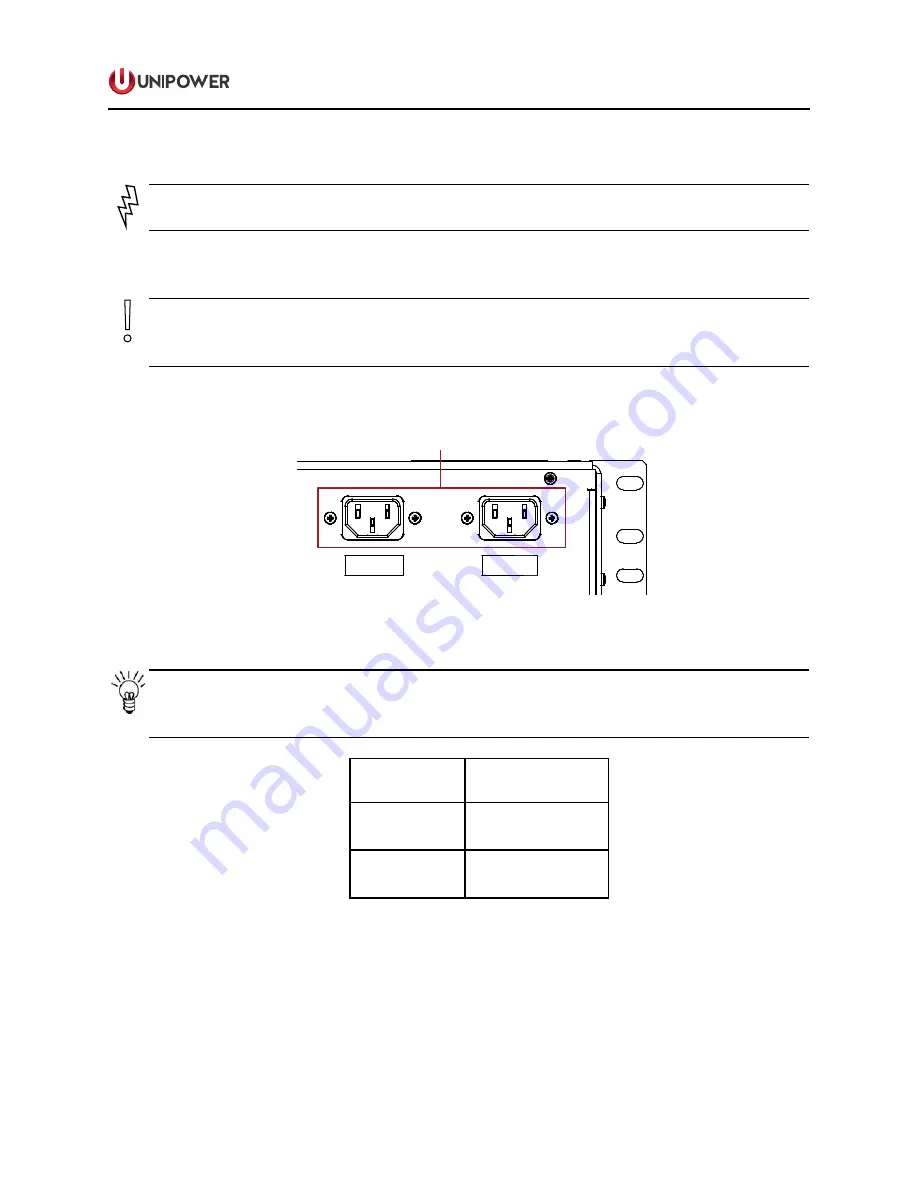
AC connectors are situated on the right rear side of the system shown in Figure 4-4.
4
3
2
1
LOAD
+
_
+
_
+
_
+
_
BATTERY
+
_
AC INPUT 2
AC INPUT 1
SIGNAL
CONNECTIONS
BATTERY
AC
INPUTS
DC
OUTPUTS
+
-
+
-
+
-
+
_
Figure 4-4 Mains Connection (viewed from rear)
NOTE
AC inputs are independent and feed only the associated rectifier slot; i.e. AC Input
1 feeds rectifier slot 1 and AC Input 2 feeds rectifier slot 2.
Connect AC power cords to the same or separate feeds as desired.
Rectifiers
in branch feed
Mains Breaker
2
25A for 120VAC
16A for 250VAC
1
12A for 120VAC
8A for 250VAC
Table 4-1 Recommended Mains Circuit Protection
4.5.3 Alarm and Signal Connections
Alarm and Signal connections are positioned on the left rear side of the Power Shelf, see
Figure 4-3.


