Page 26
P O W E R I N G T E C H N O L O G Y
Manual No. PM110-6500-00 rev-2a
PM110-6500-00-rev2a-0117.indd
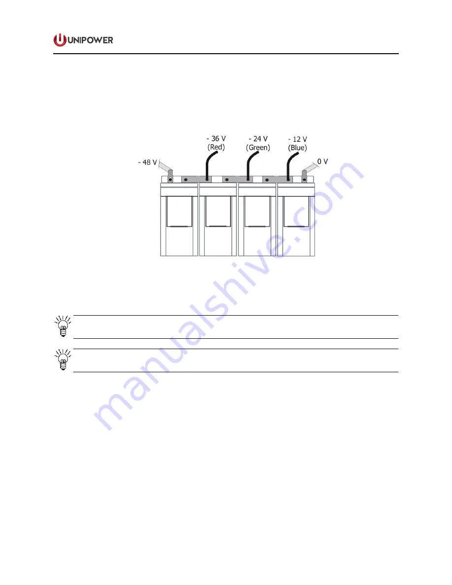
3. Fix the 3 wires (red, green and blue) of the symmetry cable to individual cable lugs.
Color coding of the cables must be respected for proper symmetry measurement see
Figure 4-9.
Figure 4-9 Symmetry Measurement (for illustration only)
NOTE
The
i
nter-block Connection Kit is not delivered with the system.
NOTE
See Figures 4-5 and 4-6 for connection to the system.
4.5.7 Temperature Sensor Connection
Temperature sensor connections for supervising battery temperature and measuring ambient
temperature are made using three-pin plugs according to the same procedure as for the alarm
connections.
For battery temperature measurement the sensor itself should be fastened to the battery after
battery installation: Unwind the cable, remove the paper covering the adhesive for the sensor
and fasten the sensor to the battery as shown in Figure 4-10.


