background image

Operation 


Sageon II Bulk Product Manual 


PM990-5201-00, Issue 6 

5-2  


RECT

BATT

LOG

INC

DEC

ENTER


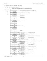
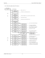
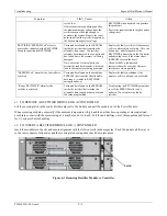
Apart from the base menu (system parameters), there are three other menus that can be accessed by momentarily pressing the 
relevant pushbuttons: 
 

a)


RECT

IFIER menu, which includes the rectifier related programmed parameters as well as the output current and 

heat-sink temperature for each rectifier; 

b)


BATT

ERY menu in which all the parameters relating to the batteries are found; 

c)


LOG

 which stores the individual alarm event information together with date and time starting with the most recent 

alarm. A total of 100 alarms are stored. 

5.2.3


Status Indicating LEDs (Controller) 

All LEDs off, indicates the unit is off due to either DC 
power not present, or there is an internal failure of 
Controller 
The amber LED indicates any alarm condition, either 

system or rectifier related. 
The red LED indicates that one or more of the rectifiers in the system is shut down. 

5.3


CONTROLLER SECURITY & ALARMS 

5.3.1


Password security 

Controller features password security for setting of parameter. A valid password is an alphanumerical code having minimum 
three and maximum eight characters. 
Units leave the factory without a pre-programmed password and the security function is not active. To activate the security, a 
password must be programmed. Once that is done, security can be enabled.  

5.3.1.1


Entering a password to gain access to parameters change 

When the security function is active, any changes to the system settings can be done only after a valid password was entered. 
When the ENTER key is pressed to change a parameter, the display will show a message “Enter Password” on the top line 
and a blinking cursor on the right hand side of the bottom line. Using INC and DEC keys scroll to the first character of the 
password and press ENTER. The character will be substituted by an asterisk (*) displayed to the left of the cursor. Enter all 
characters of the password the same way. If the password is less than eight characters long press ENTER again after last 
character. If the entered password was correct, the display will return to the selected parameter ready for modification.  If the 
entry was incorrect, the following will be displayed. 

Wrong Password    

Panel Locked


There is no limit on password entry re-tries. To abort password entry any of the top row buttons should be pressed. The 
display will return to the selected parameter.  Once unlocked, the security is disabled until there is no keypad activity for >1 
minute. 

5.3.2


When an alarm condition exists 

If one or more alarm conditions exist at any time, the following message will alternate with the “home” screen for 2 seconds 
every six seconds in addition to warning LED indicators:  

3 Alarms 

Press ENTER 

SYSTEM OK 


Green LED 

ALARM 

Amber LED 

RECTIFIER SHUTDOWN 


Red LED 

Summary of Contents for Sageon II

Page 1: ...nual PM 990 5201 00 Issue 6 sageon2_48 man pdf UNIPOWER LLC 3900 Coral Ridge Drive Coral Springs FL 33065 United States Tel 954 346 2442 Fax 954 340 7901 Email customer services unipowerco com Web sit...

Page 2: ......

Page 3: ...of shipment open the container and inspect the contents for damage If it is necessary to move or otherwise handle the shipment refer to the next section Handling for instructions and warnings Unpack t...

Page 4: ...wn in italic in the label drawing below in all correspondence with UNIPOWER A sample nameplate is shown below 225 8001 00 SAGEON II POWER MODULE PART NUMBER 110 5201 INPUT RATING 85 300VAC 18A max 45...

Page 5: ...bited Copyright UNIPOWER LLC 2015 DISCLAIMER Data descriptions and specifications presented herein are subject to revision by UNIPOWER LLC without notice While such information is believed to be accur...

Page 6: ...ANSION MODULES 3 10 4 COMMISSIONING 4 1 5 OPERATION 5 1 5 1 SUMMARY OF CONTROLLER FRONT PANEL CONTROLS 5 1 5 2 CONTROLLER COMPONENTS 5 1 5 2 1 Alpha numeric Display 5 1 5 2 2 Front Panel Pushbuttons 5...

Page 7: ...board connections 2 4 Figure 3 1 Mount points for securing Power Module in a rack 3 1 Figure 3 2 AC Feed Terminations 3 2 Figure 3 3 Single Phase feed phase to neutral 3 3 Figure 3 4 Single Phase fee...

Page 8: ......

Page 9: ...ivalent standard For open rack use the back of the magazine must be fully enclosed by its covers and the AC wiring terminations must be protected by either a grounded casing or an enclosure that provi...

Page 10: ......

Page 11: ...sed The Power Module provides the following integrated features Bulk power N 1 redundant rectifiers battery charge current limiting opt short circuit and reverse polarity protection battery temperatur...

Page 12: ...Configuration Sageon II Bulk Product Manual PM990 5201 00 Issue 6 2 2 Figure 2 3 400A Bulk Power with AC Breakers Figure 2 4 600A Bulk Power with AC Breakers...

Page 13: ...ribbon 7 Standalone system voltage connection Controller power and voltage sensing 8 Load circuit breaker trip detection circuitry connection Notes Devices and cable connections are pre wired as part...

Page 14: ...Figure 2 7 Alarm relay board connections The alarm relay board is installed on the side of the Power module such that Relay 5 is on the top when viewed from the rear of the metalwork Each alarm is us...

Page 15: ...ilarly the energy hazard associated with the batteries connected to the DC bus must be addressed with appropriately insulated tools and other measures to prevent accidental short circuits to the DC bu...

Page 16: ...feed is individually protected and the installer is only required to connect a single AC supply 1 phase to the AC DIN rail terminations 3 3 MAINS CONNECTIONS Figure 3 2 AC Feed Terminations 3 3 1 Fac...

Page 17: ...Installation Sageon II Bulk Product Manual PM990 5201 00 Issue 6 3 3 Figure 3 3 Single Phase feed phase to neutral Figure 3 4 Single Phase feed phase to phase...

Page 18: ...Installation Sageon II Bulk Product Manual PM990 5201 00 Issue 6 3 4 Figure 3 5 split Single Phase feed phase to neutral Figure 3 6 Y Three Phase feed connected rectifiers phase to phase...

Page 19: ...Installation Sageon II Bulk Product Manual PM990 5201 00 Issue 6 3 5 Figure 3 7 Y three Phase feed phase to neutral Figure 3 8 three Phase feed phase to phase...

Page 20: ...tion Sageon II Bulk Product Manual PM990 5201 00 Issue 6 3 6 Figure 3 9 Y three phase feed Single Phase to rectifiers phase to phase Figure 3 10 Y Three Phase Feed Single Phase to Rectifiers phase to...

Page 21: ...ses Other arrangements for 3 phase Y with similar levels of protection are also possible as shown below The voltage rating of the arrestor should be selected based on the maximum AC voltage likely to...

Page 22: ...s Locate the ambient sensor close to the intake air zone of the Power Module Locate the battery sensor on a battery block in the middle Module of the battery bank likely hot zone 3 7 AUXILIARY RELAY C...

Page 23: ...a rate 9600bps termination of the line with resistors generally is not required However if high rate of data corruption is experienced slow data update in monitoring program line termination resistors...

Page 24: ...All boards are factory wired and allow for easy customer connection access Figure 3 14 AC Option Box Rear View screens removed for clarity 3 12 ADDING AUXILIARY EXPANSION MODULES Modules such as the S...

Page 25: ...attery charging current limit to 10 of the Ah rating i e if 150Ah battery is used set the limit to 15A this value can be adjusted later to meet your specific charging requirements In many cases these...

Page 26: ......

Page 27: ...parameter press ENTER the value will flash on and off To increase the number press INC to decrease the number press DEC When the desired number is on the screen press ENTER again To change parameters...

Page 28: ...rd must be programmed Once that is done security can be enabled 5 3 1 1 Entering a password to gain access to parameters change When the security function is active any changes to the system settings...

Page 29: ...act failure A No Demand Control loop in RECTIFIER not in normal state A H S Temp High RECTIFIER heatsink temperature too high where available A Temp Sensor Fail Temp sensor in RECTIFIER faulty S C or...

Page 30: ...ected or failure A Batt I Limit Battery charging current is being limited to preset value A Bat Sym Alarm Battery discharge currents from battery strings not sharing load equally A Earth Leak Alarm Ea...

Page 31: ...etup Press ENTER Modify Value up down ENTER to accept Press ENTER to begin flashing display and LEDs Test Indicators Press ENTER ENTER System information including controller software version S N and...

Page 32: ...Value up down ENTER to accept ENTER Phone 3 0398887788 Modify Value up down ENTER to accept ENTER Phone 3 Cont 2323 Modify Value up down ENTER to accept ENTER Audio Alarm Off INC DEC toggles state EN...

Page 33: ...4 cells Modify Value up down ENTER to accept ENTER Number of battery banks BCM Batteries 1 Modify Value up down ENTER to accept ENTER Cell Vhi Alarm 2 50V Modify Value up down ENTER to accept ENTER Ce...

Page 34: ...not be adjusted here Equalise Voltage SMR Default SMR Equalise 56 5V Cannot be adjusted here ENTER SMR voltage above which alarm flagged SMR V high Alarm 57 0V Modify Value up down ENTER to accept ENT...

Page 35: ...Battery Rating 500Ah Modify Value up down ENTER to accept ENTER Battery Temperature compensation BTC Coeff 3 2 mV C C Modify Value up down ENTER to accept Variable from 0 to 6 0mV C C If BTC not Off...

Page 36: ...ion EQ Duration 3 hours Modify Value up down ENTER to accept ENTER Periodic equalisation charging trigger EQ Period 12 Weeks Modify Value up down ENTER to accept Set to zero to disable ENTER Manual co...

Page 37: ...ting to Closed or Auto Power up the rectifiers and reduce the load until the bus voltage increases to the float voltage Load or Battery circuit breaker alarm does not set when the breaker is opened or...

Page 38: ...A rectifier is indicating RECTIFIER Off or No Response on the Controller RECTIFIER display An AC failure to the rectifier is the most likely cause While the rectifier internal power rails are still a...

Page 39: ...rical interference where possible EEPROM Fail alarm for the Controller is activated Corrupted data found on the backplane EEPROM that is outside the allowable data range similar to RECTIFIER corruptio...

Page 40: ......

Page 41: ...new IP address Select correct network class Click Set IP Address button The process takes several seconds to complete and the progress is indicated below IP address field When completed a dialog box...

Page 42: ...just press Enter if N press Y followed by enter Next item will be Gateway IP address nnn Enter assigned gateway address then press Enter at each item until set up menu is shown again Terminate Telnet...

Page 43: ...P address you just set is temporary and will revert to the default value when the unit s power is reset unless you log into the unit and store the changes permanently Refer to the chapter on configura...

Page 44: ...to the unit basic parameters Hardware Ethernet Autodetect IP addr 192 168 000 098 no gateway set Select 0 and press Enter to configure the Lantronix Interface Server s basic parameters IP Address The...

Page 45: ...t Can sustain short circuit at output terminals indefinitely Reverse Battery Polarity Internal fuse at output of RECTIFIER High Voltage Shutdown Rectifier shuts down if output exceeds programmed overv...

Reviews: