


Troubleshooting
Sageon II Bulk Product Manual
PM990-5201-00, Issue 6
6-1
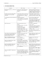
6.
TROUBLESHOOTING
Symptom Likely
Causes Action
Rectifiers do not power up – no LEDs lit on
front panel
AC power is not connected or internal
fuse blown or rectifier not properly
plugged in.
Re-insert rectifier(s) and make sure the
rear connections are good. Confirm that
AC power is available to the rectifier
backplanes. Replace the rectifier module
if the unit is suspected to have failed.
No output current from rectifiers and the
Green LED on each rectifier blinks
occasionally
AC power either <70VAC or >320VAC.
An internal relay will be heard open and
close periodically if the AC voltage is
excessive.
Check that the AC supply voltage and
connection arrangement are correct and
match the expected system supply wiring.
Over-temperature alarm or fan failure alarm
present
High ambient temperature.
Fan air intake/exhaust vents are blocked
or a fan is jammed with a foreign object
or excessive dust.
Check the ambient temperature and
improve site cooling if possible.
Check and remove obstructions from the
air vents. Replace the module or remove
and replace the fan assemblies in the
module (requires only that the rectifier lid
be removed)
BLVD will not close
One or more batteries are reverse
polarity.
No battery is connected to the battery
distribution module.
Fuse link blown in the battery
distribution module (BDM).
Controller setting for LVDS is “Open”.
Controller setting for LVDS is “Auto”
and the DC bus voltage was < LVDS trip
threshold and has not increased to the
float voltage.
Check battery wiring polarity.
Connect a battery.
Check that the Controller is powered up
even when no rectifier is operational. If
not, service the fuses in the BDM.
Change the Controller LVDS setting to
“Closed” or “Auto”.
Power up the rectifiers and reduce the
load until the bus voltage increases to the
float voltage.
Load or Battery circuit breaker alarm does
not set when the breaker is opened or is
incorrectly alarmed as battery switch
instead of load trip or visa-versa.
No battery or load is connected to the
circuit breaker connection.
Alarm link in BDM is incorrectly
configured.
Check load and battery connections to the
BDM and that the alarm links are
correctly configured.
Battery or Ambient temperature sensor
reading is indicated as “Not Available”
Sensor / cable faulty.
Sensor connector reversed.
No sensor installed.
Turn cable connector around and
reconnect.
Replace faulty sensor assembly.
Battery current indicated does not match
independent measurement.
Full-scale current of the DC hall effect
current transducer is incorrectly set and
will result in an error larger than +/- 5%
at more than 50% full-scale current.
Change the setting of the “FS Batt Curr”
value in the Base Menu of Controller to
the correct full-scale value.
Battery current indicates 0A when more
than 5A is flowing in the battery or is
inaccurate at low currents (<5A)
DC hall effect transducer or wiring is
faulty.
Current transducer sensitivity is too low
for 1A measurement
Service the DC current transducer in the
BDM – check the wiring is intact and still
connected properly, or replace the DC CT
is suspected to be faulty
Revise size of DC CT full-scale value for
the size of the load and battery charging
requirements.
Load current indicates 0A when known to
be >5A
Number of RECTIFIERs is incorrectly
set too low or the battery current FS is set
too high. The load current is calculated
from the sum of the RECTIFIER currents
minus the measured battery currents
Check that the number of RECTIFIERs
in the Controller Base menu matches the
actual number of rectifier modules
installed.
Check the Battery DC CT rated full-scale
value is correctly set in the Base menu.