


Troubleshooting
Sageon II Bulk Product Manual
PM990-5201-00, Issue 6
6-2
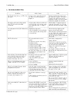
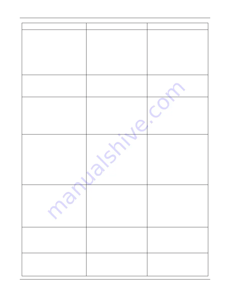
Symptom Likely
Causes Action
One unit is alarmed as HVSD (high voltage
shutdown) and is latched off.
The unit has developed a fault that causes
it to output a voltage above the HVSD
protection limit and has been supplying
load current while above this voltage
limit.
A random event on the DC bus has
occurred that forced a unit into HVSD.
Replacing the rectifier module is
recommended. However, a random event
may have triggered the HVSD and to
determine if the unit has a real fault, the
HVSD latched alarm can be reset using
the “Reset Latched Alarm” function in
the Controller RECTIFIER Menu. (If the
system does not have any batteries,
cycling the AC power will have the same
effect). If the unit does not recover by
latching off again, it is faulty.
“RECTIFIER Urgent” alarm activated
One or many RECTIFIERs are off due to
AC power failure, internal faults,
incorrect command signal from
Controller or all rectifiers are in current
limit
Check the AC power and restore.
Replace faulty rectifier modules.
Check for DC bus overload faults.
All units are latched off as HVSD
Absolute Overvoltage shutdown
protection activated. The system is likely
to have no load and without a battery.
An event on the DC bus has caused the
voltage to exceed 70V for 48V systems
or 35V for 24V systems. The event
could be caused either by a faulty
rectifier or other equipment connected to
the bus.
Add a small amount of load (>2A per
rectifier) to the system and check for a
faulty rectifier.
Check for other faulty equipment
connected to the bus that could cause the
overvoltage transient.
Use the “Reset Latched Alarm” from the
Controller to reset the system.
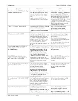
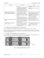
A rectifier is indicating “RECTIFIER Off”
or “No Response” on the Controller
RECTIFIER display
CONTINUE: A rectifier is indicating
“RECTIFIER Off” or “No Response” on
the Controller RECTIFIER display
An AC failure to the rectifier is the most
likely cause. While the rectifier internal
power rails are still available, the unit
will communicate with “RECTIFIER
Off” if the AC has failed on its input.
Once the internal power dies, the unit
will no longer communicate and
Controller will indicate “No Response”.
“No Response” all the time and the
RECTIFIER is known to have AC power
indicates a communications wiring
problem.
Check the AC feed to the rectifier for a
tripped circuit breaker, blown fuse or
faulty connection.
Check the RECTIFIER communications
10-way ribbon cable for broken
connections and replace cable if
necessary.
One or more rectifiers has a current limit or
power limit alarm activated
Total load, including battery-charging
current is equal to the output limits of the
rectifiers. (System overload)
One rectifier in current limit only
indicates a likely calibration problem
with the module. The Controller can
usually compensate for an out of
calibration unit in a system and will take
a few minutes to adjust the unit to
correctly share the load.
Revise the load level on the system and
expand the number of rectifiers as
required to remove the overload
condition.
One rectifier has an “UNCAL RECTIFIER”
alarm
The Controller has not been able to make
the unit share the load with the other
units. Either the RECTIFIER is faulty
(excessive internal voltage drop) and
cannot be adjusted to share load, or it is
too far out of calibration.
Replace the rectifier module. Send the
unit for repair and re-calibration.
“System Voltage Clamp” alarm activated
Controller cannot reach the desired
system voltage. This can be due to
possible excessive voltage drop along the
DC bus bars, inside one or more rectifiers
or “System V Drop” parameter has been
Increase “Sys V Drop” parameter.
Replace faulty rectifier (unlikely to
current share as well).
Check that the number of RECTIFIERs
in the system is correctly set (more


