background image

Page 11

DPU1U SERIES

INSTALLATION & OPERATING MANUAL

P O W E R I N G   T E C H N O L O G Y

Document Number: DPU1U-MAN Rev. 4

dpu1u-man-rev1-0719.indd


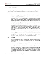
Figure 9 shows the back combination panel with two distribution sections fitted.  Inputs 

are at the left and right ends of the back panel.  Side B outputs are at two rows of barrier 
terminal strips on the left side, and side A outputs are the same on the right side.


Alarm

Contacts

Alarm LEDs

B Input

¼-20 Studs

BAT

RTN

BAT

RTN

1   2   3   4   5   6   7   8   9   10

A

B

ALARM

Ground

8-32 Stud

A Side Breakers

B Side Breakers

A Outputs

6-32 Terminal Strip

B Outputs

6-32 Terminal Strip

A Input

¼-20 Studs

BAT

RTN

BAT

RTN

1   2   3   4   5   6   7   8   9   10

B SIDE A SIDE

NO-C-NC

NO-C-NC

5

6

3

4

1

2

OFF

O

ON

I

15

OFF

O

ON

I

15

OFF

O

ON

I

15

OFF

O

ON

I

15

OFF

O

ON

I

15

OFF

O

ON

I

15

5

6

3

4

1

2

OFF

O

ON

I

15

OFF

O

ON

I

15

OFF

O

ON

I

15

OFF

O

ON

I

15

OFF

O

ON

I

15

OFF

O

ON

I

15

17.12 (434.9)

1.74

(44.2)

REAR VIEW

FRONT VIEW

Case depth: 8.94 (227.1)

2.28

(57.8)

Clear Perspex

Safety Cover

Figure 9.  Back Panel View with Dual Distribution


At the center of the back panel are two spring clamp terminal blocks for the Form C relay 
contact outputs.  Below these is a chassis ground terminal.

9.2 

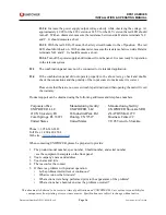
Input Connections (also Output Connections for LVD)

. See Figure 10. The DC power 

inputs to the combination panels are made by means of crimp type lugs or direct connection 

to ¼-20 studs to two copper bus bars on side A and side B.  The upper bus bar is the battery 

connection (w or -) and the lower bus bar is the return (w or -).

0.625”

1.48”

0.5”

0.34”

0.375”

0.65”

0.32”

Figure 10.  Input Bus Bar Detail
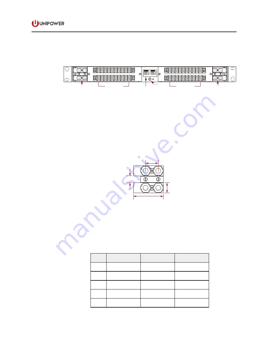
9.3 

Crimp Type Lugs. 

A list of compatible crimp type lugs is shown in the following table 

for AWG wire sizes from no. 1 to 8 and one- or two- hole lugs.  These lugs can be ordered 
directly from the manufacturer, Panduit Corp., using the model numbers shown in table 4.


A standard kit of four two-hole crimp type lugs for no. 6 AWG copper wire is available from 
UNIPOWER.  Order kit no. 775-1434-0000.

WIRE

AWG

.25DIA.

HOLES

PANDUIT CORP.

PART NUMBER

UNIPOWER

PART NUMBER

8

1
2

LCA8-14-L

LCD8-14A-L

625-1665-0010

625-1665-0110

6

1
2

LCA6-14-L

LCD6-14A-L

625-1665-0020
625-1665-0120

4

1
2

LCA4-14-L

LCD4-14A-L

625-1665-0030
625-1665-0130

2

1
2

LCA2-14-Q

LCD2-14A-Q

625-1665-0040
625-1665-0140

1

1
2

LCA1-14-E

LCD1-14A-E

625-1665-0050
625-1665-0150

Table 4.  Input Cable Lug Sizes & Types

Summary of Contents for UNIFLEX DRU1U Series

Page 1: ...y can be mounted from the front of the rack with offsets every quarter inch from front to back to align with existing rack mounted equipment FEATURES One Mounting Position High 1 75 19 or 23 Inch Rack...

Page 2: ...w voltage disconnect specified by L 2 A bypass switch must also be designated YES or NO 3 For a breaker panel each breaker must be specified with highest current in position 1 down to lowest current i...

Page 3: ...N PANELS Document Number DPU1U MAN Rev 4 UNIPOWER LLC 65 Industrial Park Rd Dunlap TN 37327 Phone 1 954 346 2442 Toll Free 1 800 440 3504 Web site www unipowerco com 2019 UNIPOWER LLC All Rights Reser...

Page 4: ...TRODUCTION 4 2 0 FEATURES 5 3 0 PRODUCT DESCRIPTION 5 4 0 SAFETY INDUSTRY STANDARDS 6 5 0 WARRANTY summary 6 6 0 DESCRIPTION OF OPERATION 7 7 0 SPECIFICATIONS 8 8 0 FRONT PANEL DESCRIPTION 9 9 0 BACK...

Page 5: ...MT Fuse Section Front Panel View 9 Figure 6 LVD Front Panel View 9 Figure 7 Center Section Front Panel View 9 Figure 8 Back Panel View with LVD 10 Figure 9 Back Panel View with Dual Distribution 11 Fi...

Page 6: ...ng rackmounted equipment DPU1U Series provides a combination of circuit breaker or fuse distribution on the A side with an LVD or distribution on the B side Figure 1 shown the three possible combinati...

Page 7: ...GMT Fuses or Magnetic Circuit Breakers LVD Protection 70A Magnetic Circuit Breaker with Bypass Option Independent and Isolated Loads Input Connections Crimp Type Lugs Output Connections Barrier Termi...

Page 8: ...operating these combination anels the chassis ground terminal must be connected to the system frame ground or other proper safety ground for the protection of personnel 4 5 All connections to these co...

Page 9: ...S OPTION Figure 2 Distribution Block Diagram 6 2 LVD Circuits Figure 3 shows a simplified diagram of the LVD circuit The LVD is connected to a rectifier bus battery and distribution panel The contact...

Page 10: ...Alarm Indicator LED on Each Side LED Status Fuse Breaker Sections Green Normal Red Alarm Off No Power LVD Section Red LVD Contactor or Battery Breaker Open Off Normal Alarm Connections Fuse Breaker Tw...

Page 11: ...F O ON I 15 17 12 434 9 REAR VIEW FRONT VIEW Cas Figure 4 Distribution Section Front Panel View The front panel of the GMT fuse distribution section shown in Figure 5 below can each accommodate up to...

Page 12: ...Red 3 401 1500 0060 Blue 401 1500 0020 Brown 5 401 1500 0070 Green 1 401 1500 0030 Gray 10 401 1500 0080 Red White 11 3 401 1500 0040 White 12 401 1500 0090 Green Yellow 2 401 1500 0050 Orange DUMMY...

Page 13: ...o spring clamp terminal blocks for the Form C relay contact outputs Below these is a chassis ground terminal 9 2 Input Connections also Output Connections for LVD See Figure 10 The DC power inputs to...

Page 14: ...mum of two high current breakers is allowed 1 2 3 4 5 6 7 8 9 10 40 50A LOADS 10 32 1A to 30A LOADS 6 32 0 75 19 1 0 5 12 7 0 378 9 60 Figure 11 Output Barrier Strip Detail 9 5 Form C Relay Contact Ou...

Page 15: ...is either loss of input power one or more circuit breakers trip or the relay is de energized the normally open contacts close and the normally closed contacts open See table 6 RELAY STATE MEANINGS Rel...

Page 16: ...Mount it from the front of the rack using the correct offsets to align with existing rack mounted equipment The bracket offsets are every quarter inch from front to back 11 2 Power Connections Input c...

Page 17: ...asure the resistance between C and N O This which should read open Measure the resistance between C and N C This should read short Replace the blown fuse with a good one or reset the circuit breaker 1...

Page 18: ...d application 12 4 If the combination panel did not operate properly in the above tests go back and double check the connections and the polarity of the input source to make sure it is correct Please...

Reviews: