background image

Page 13

DPU1U SERIES

INSTALLATION & OPERATING MANUAL

P O W E R I N G   T E C H N O L O G Y

Document Number: DPU1U-MAN Rev. 4

dpu1u-man-rev1-0719.indd
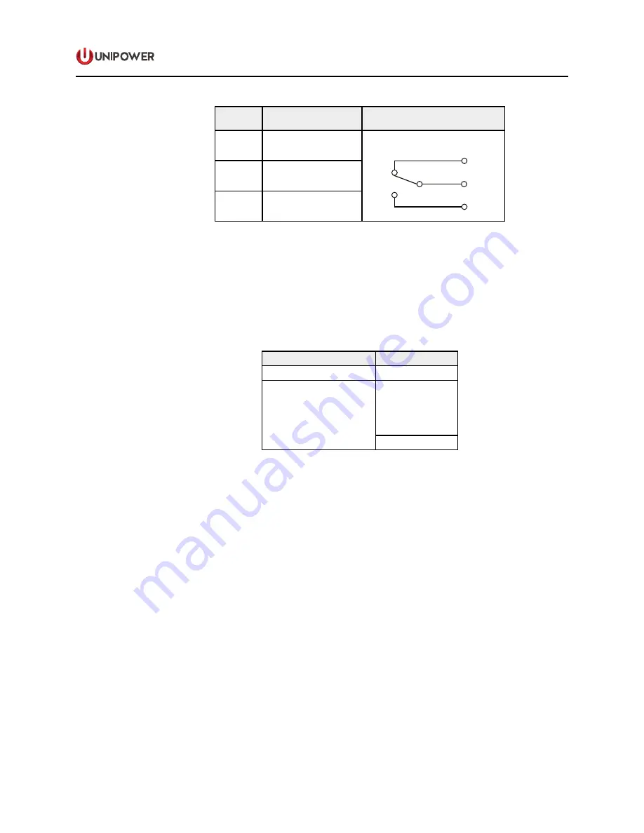
PIN

FUNCTION

CONTACT SCHEMATIC

NC

N.C. (normally closed)

RELAY

CONTACTS

OUTPUTS

N.C.

C     

N.O.

C

C (common)

NO

N.O. (normally open)


Table 5.  Alarm Relay Contacts


“Normally Closed” and “Normally Open” are defined with the combination panel powered 

and providing power to all outputs, i.e. no circuit breakers tripped AND when the input 
power is connected to a side (A or B), the Form C relay of that side is energized.  If there 
is either loss of input power, one or more circuit breakers trip or the relay is de-energized, 
the normally open contacts close and the normally closed contacts open.  See table 6. 

RELAY STATE MEANINGS

Relay State

Meaning

Energized (N.C. is closed)

OK

De-energized 

(N.C. is open)

Breaker Trip

or

Breaker OFF

or

Fuse Blown

No Input Power

Table 6.  Relay State Definitions


The ratings of the relay contacts are 0.6A at 125VAC or 2A at 30VDC.   The spring clamp 
terminals accept wire sizes nos. 16 to 26 AWG.

9.6 

Chassis Ground Connection.

  Just below the Form C relay contact terminals is the chassis 

ground terminal.  This terminal is a no. 8-32 stud with a nut.


NOTE THAT IT IS ESSENTIAL THAT THIS TERMINAL IS CONNECTED TO THE 
SYSTEM FRAME GROUND TO ENSURE SAFE OPERATION.

Summary of Contents for UNIFLEX DRU1U Series

Page 1: ...y can be mounted from the front of the rack with offsets every quarter inch from front to back to align with existing rack mounted equipment FEATURES One Mounting Position High 1 75 19 or 23 Inch Rack...

Page 2: ...w voltage disconnect specified by L 2 A bypass switch must also be designated YES or NO 3 For a breaker panel each breaker must be specified with highest current in position 1 down to lowest current i...

Page 3: ...N PANELS Document Number DPU1U MAN Rev 4 UNIPOWER LLC 65 Industrial Park Rd Dunlap TN 37327 Phone 1 954 346 2442 Toll Free 1 800 440 3504 Web site www unipowerco com 2019 UNIPOWER LLC All Rights Reser...

Page 4: ...TRODUCTION 4 2 0 FEATURES 5 3 0 PRODUCT DESCRIPTION 5 4 0 SAFETY INDUSTRY STANDARDS 6 5 0 WARRANTY summary 6 6 0 DESCRIPTION OF OPERATION 7 7 0 SPECIFICATIONS 8 8 0 FRONT PANEL DESCRIPTION 9 9 0 BACK...

Page 5: ...MT Fuse Section Front Panel View 9 Figure 6 LVD Front Panel View 9 Figure 7 Center Section Front Panel View 9 Figure 8 Back Panel View with LVD 10 Figure 9 Back Panel View with Dual Distribution 11 Fi...

Page 6: ...ng rackmounted equipment DPU1U Series provides a combination of circuit breaker or fuse distribution on the A side with an LVD or distribution on the B side Figure 1 shown the three possible combinati...

Page 7: ...GMT Fuses or Magnetic Circuit Breakers LVD Protection 70A Magnetic Circuit Breaker with Bypass Option Independent and Isolated Loads Input Connections Crimp Type Lugs Output Connections Barrier Termi...

Page 8: ...operating these combination anels the chassis ground terminal must be connected to the system frame ground or other proper safety ground for the protection of personnel 4 5 All connections to these co...

Page 9: ...S OPTION Figure 2 Distribution Block Diagram 6 2 LVD Circuits Figure 3 shows a simplified diagram of the LVD circuit The LVD is connected to a rectifier bus battery and distribution panel The contact...

Page 10: ...Alarm Indicator LED on Each Side LED Status Fuse Breaker Sections Green Normal Red Alarm Off No Power LVD Section Red LVD Contactor or Battery Breaker Open Off Normal Alarm Connections Fuse Breaker Tw...

Page 11: ...F O ON I 15 17 12 434 9 REAR VIEW FRONT VIEW Cas Figure 4 Distribution Section Front Panel View The front panel of the GMT fuse distribution section shown in Figure 5 below can each accommodate up to...

Page 12: ...Red 3 401 1500 0060 Blue 401 1500 0020 Brown 5 401 1500 0070 Green 1 401 1500 0030 Gray 10 401 1500 0080 Red White 11 3 401 1500 0040 White 12 401 1500 0090 Green Yellow 2 401 1500 0050 Orange DUMMY...

Page 13: ...o spring clamp terminal blocks for the Form C relay contact outputs Below these is a chassis ground terminal 9 2 Input Connections also Output Connections for LVD See Figure 10 The DC power inputs to...

Page 14: ...mum of two high current breakers is allowed 1 2 3 4 5 6 7 8 9 10 40 50A LOADS 10 32 1A to 30A LOADS 6 32 0 75 19 1 0 5 12 7 0 378 9 60 Figure 11 Output Barrier Strip Detail 9 5 Form C Relay Contact Ou...

Page 15: ...is either loss of input power one or more circuit breakers trip or the relay is de energized the normally open contacts close and the normally closed contacts open See table 6 RELAY STATE MEANINGS Rel...

Page 16: ...Mount it from the front of the rack using the correct offsets to align with existing rack mounted equipment The bracket offsets are every quarter inch from front to back 11 2 Power Connections Input c...

Page 17: ...asure the resistance between C and N O This which should read open Measure the resistance between C and N C This should read short Replace the blown fuse with a good one or reset the circuit breaker 1...

Page 18: ...d application 12 4 If the combination panel did not operate properly in the above tests go back and double check the connections and the polarity of the input source to make sure it is correct Please...

Reviews: