


Page 4
DPU1U SERIES
INSTALLATION & OPERATING MANUAL
P O W E R I N G T E C H N O L O G Y
Document Number: DPU1U-MAN Rev. 4
dpu1u-man-rev1-0719.indd
OPERATING MANUAL
DPU1U SERIES COMBINATION PANELS
1.0 INTRODUCTION
DPU1U Series combination panels provide protected power distribution to telecommunication
equipment. They are only 1.75 inches (1 mounting position) high to minimize rack space and
can be mounted in either a 19- or 23-inch relay rack with corresponding brackets. They can be
mounted from the front of the rack with offsets every ¼-inch from front to back to align with existing
rackmounted equipment.
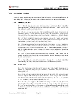
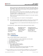
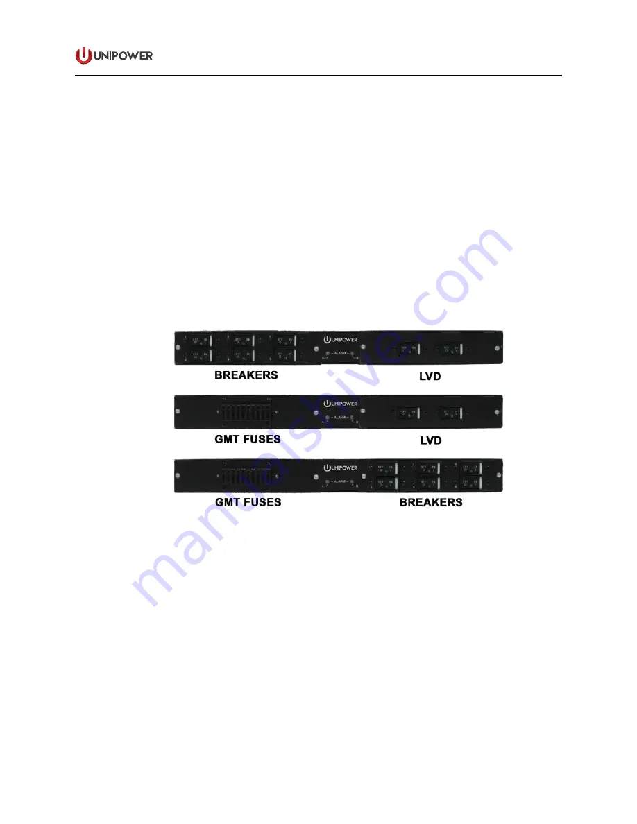
DPU1U Series provides a combination of circuit breaker or fuse distribution on the A side with an
LVD or distribution on the B side. Figure 1 shown the three possible combinations.
.
Figure 1. DPU1U Alternative Combinations
The DPU1U Series panels can be configured for 12, 24 or 48 volts with either positive or negative
ground. Because the A and B sides are independent and isolated, they can be configured separately.
For example, the A side can be 48V positive ground and the B side can be 24V negative ground.
The voltage and polarity of each side must be configured at the factory. All models are reverse
polarity protected.
Each load (A and B) has a green/red visual alarm and two Form C relay alarm contacts for connection
to external audible or visual alarms.


