Page 7
DPU1U SERIES
INSTALLATION & OPERATING MANUAL
P O W E R I N G T E C H N O L O G Y
Document Number: DPU1U-MAN Rev. 4
dpu1u-man-rev1-0719.indd
6.0
DESCRIPTION OF OPERATION
6.1
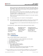
Power Distribution Circuits.
A simplified schematic diagram of the distribution panels
is shown in Figure 2. The battery input to each load connects to a high-current copper bus
bar from which the individual fuses or circuit breakers distribute power to the loads. The
return input connects to a similar bus bar to which the individual loads terminate. The A
and B loads are totally independent and isolated with the exception of models incorporating
the ‘S’ option.
CIRCUIT
BREAKERS
or
GMT FUSES
BATT.
BATT.
INPUT
RET.
INPUT
RET.
HI-CURRENT BUS BAR
HI-CURRENT BUS BAR
HI-CURRENT BUS BAR
HI-CURRENT BUS BAR
LOADS
LOADS
1
2
3...
N
N
...3
2
1
A SIDE
ALARM
CIRCUITS
b SIDE
ALARM
CIRCUITS
A SIDE
B SIDE
-S OPTION
-S OPTION
Figure 2. Distribution Block Diagram
6.2
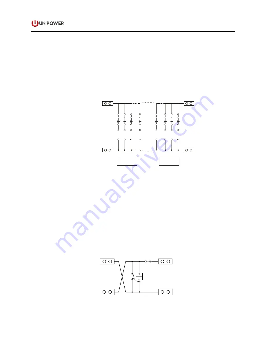
LVD Circuits.
Figure 3 shows a simplified diagram of the LVD circuit. The LVD is
connected to a rectifier bus, battery and distribution panel. The contactor and bypass switch
can be connected either in series with the rectifier and load or the rectifier and battery. If the
battery voltage drops to 42.5V for a 48V battery or 21.25V for a 24V battery, the contactor
opens, removing the loads from the rectifier and battery or, alternatively, removing the battery
from the rectifier and loads. The disconnect contactor is rated at 70 amperes. If the current
into or out of the battery exceeds 100 amperes, the battery circuit breaker will trip. If the
contactor opens due to low voltage, it will close again when the battery voltage exceeds
49.0 volts for a 48V battery or 24.5 volts for a 24V battery. Other circuitry is incorporated
detects the low battery voltage, turns the red LED on or off and turns the Form C relay on
or off.
BATT.
LOAD
RECT. (Batt.)
RECT (Load)
100A
LVD CONTACTOR
BYPASS BREAKER
(optional)
Figure 3. LVD Block Diagram