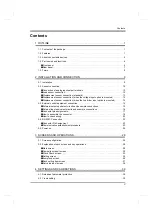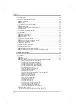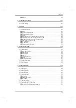
3
1
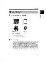
OUTLINE
3
OUTLINE
Chapter
1
●
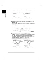
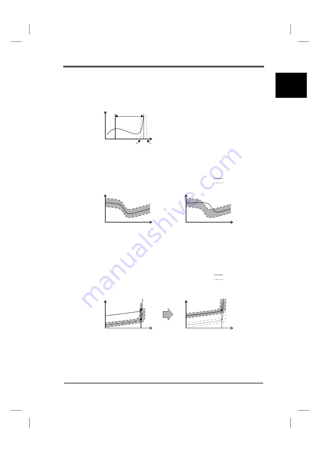
Control of the position at the measurement completion
The position of the measurement completion can be judged by using the End Displacement for
the Use Hold.
The End Displacement is different from other hold types, so it judges not based on a wave
starting point but based on an original point of the displacement.
●
Entire waveform control by using the waveform comparison function
Comparisons can be made to judge whether or not a measurement waveform is between HI limit
and LO limit waveforms.
●
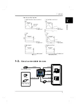
Measurement-waveform-following control by using the relative comparison function
Waveforms fluctuating up and down with each measurement can be relatively compared.
By this function, comparison waveforms are relatively moved according to the load at the
Reference Point of Relative Comparison, which should previously be set by time or
displacement, on a measurement waveform.
* Relative movement can only be made in the Y-axis direction.
●
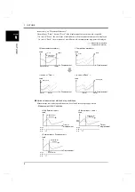
Change of the control reference to the point at which loading is started or the point at
which it is finished
In the case where the X-axis of the waveform represents displacement, the reference for the hold
function and waveform comparison function can be selected from either the measurement start
point or measurement stop point.
For the measurement start point and measurement stop point, set “Front” and “Back,”
Displacement
Load
0
10
50
Section
Measurement
LO limit of
HI limit of
displacement
displacement
< Non-defective >
Load
< Defective >
Measurement waveform
Comparison waveform
Load
Time or
displacement
Time or
displacement
< Before relative movement >
Load
< Relative movement of comparison
Load
Measurement waveform
Comparison waveform
waveforms >
Time or
displacement
Time or
displacement
Reference Point
of Relative Comparison
Reference Point
of Relative Comparison
Summary of Contents for DeviceNet F381A
Page 1: ...15APR2013REV 3 10 DYNAMIC FORCE PROCESSOR F381A OPERATION MANUAL ...
Page 9: ...Contents VIII Contents VIII M E M O ...
Page 34: ...25 2 INSTALLATION AND CONNECTION 25 INSTALLATION AND CONNECTION Chapter 2 M E M O ...
Page 147: ...138 8 SPECIFICATIONS 138 SPECIFICATIONS Chapter 8 8 2 Outside dimensions Unit mm ...
Page 164: ......


