16
2
INSTALLATION AND CONNECTION
16
INST
ALLATION AND CONNECT
ION
Chapter
2
■
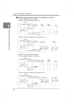
External input equivalent circuits and example connections
- In case of plus common connection
When you connect the relay and the switch, etc.
When you connect the transistor and the photocoupler, etc.
- In case of minus common connection
When you connect the relay and the switch, etc.
When you connect the transistor and the photocoupler, etc.
Ic=
Input
Input COM
F381A
Plus common connection
A1 to A8
B1 to B8
A9
,
10
B9
,
10
DC24V
+24V 0V
Push
Toggle
Switch
Switch
Relay
Approx. 5mA
Input
Input COM
F381A
Plus common connection
A1 to A8
B1 to B8
A9
,
10
B9
,
10
DC24V
+24V 0V
Photocoupler
Transistor
Ic=
Approx. 5mA
Input COM
Input
F381A
Minus common connection
A9
,
10
B9
,
10
A1 to A8
B1 to B8
DC24V
0V +24V
Push
Toggle
Switch
Switch
Relay
Ic=
Approx. 5mA
Input COM
Input
F381A
Minus common connection
A9
,
10
B9
,
10
A1 to A8
B1 to B8
DC24V
0V +24V
Photocoupler
Transistor
Ic=
Approx. 5mA
Summary of Contents for DeviceNet F381A
Page 1: ...15APR2013REV 3 10 DYNAMIC FORCE PROCESSOR F381A OPERATION MANUAL ...
Page 9: ...Contents VIII Contents VIII M E M O ...
Page 34: ...25 2 INSTALLATION AND CONNECTION 25 INSTALLATION AND CONNECTION Chapter 2 M E M O ...
Page 147: ...138 8 SPECIFICATIONS 138 SPECIFICATIONS Chapter 8 8 2 Outside dimensions Unit mm ...
Page 164: ......

