43
4
SETTINGS AND CALIBRATIONS
43
SETTINGS AND CAL
IBRATIONS
Chapter
4
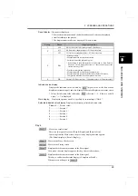
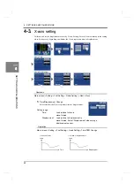
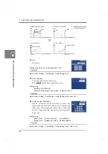
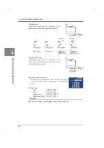
When the X-axis represents time
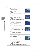
2
Measurement Length
Set the time for waveform acquisition.
Operation
Setting range (0.5, 1.0, 2.0, 5.0, 10.0 s)
Main screen
→
Setting
→
First Setting
→
X-axis Setting
→
Measure Length
When the X-axis represents displacement
2
Sensor Phase Select (standard only)
(This is not displayed when the voltage input option is used.)
Select the output phase of the displacement sensor.
Operation
Setting range (A/B-Phase, Only A-Phase)
Main screen
→
Setting
→
First Setting
→
X-axis Setting
→
Phase Select
- Only A-Phase:
A-Phase of the sensor is used. Resolution is 1 pulse.
(Positive counting only.)
- A/B-Phase:
A/B-Phase of the sensor is used. Resolution is 1/4 pulses.
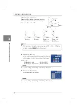
The counting conditions are as follows.
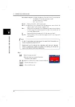
3.
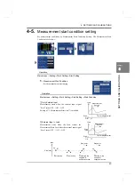
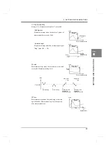
Waveform Reference
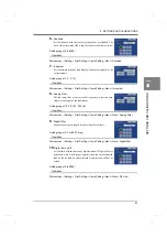
Select whether the waveform reference is front or back.
Setting range
Front: The measurement start point becomes the
waveform reference.
Operation
Back:
The measurement stop point becomes the waveform reference.
Main screen
→
Setting
→
First Setting
→
X-axis Setting
→
Wave Reference
Time
A-Phase OFF
ON
Up-counting
(When the A-phase advances)
1 pulse
B-Phase OFF
ON
A-Phase OFF
ON
Down-counting
(When the B-phase advances)
B-Phase OFF
ON
1/4 pulses
When the Waveform Reference is set at Back, Change of Section cannot be
made externally.
Point
Summary of Contents for DeviceNet F381A
Page 1: ...15APR2013REV 3 10 DYNAMIC FORCE PROCESSOR F381A OPERATION MANUAL ...
Page 9: ...Contents VIII Contents VIII M E M O ...
Page 34: ...25 2 INSTALLATION AND CONNECTION 25 INSTALLATION AND CONNECTION Chapter 2 M E M O ...
Page 147: ...138 8 SPECIFICATIONS 138 SPECIFICATIONS Chapter 8 8 2 Outside dimensions Unit mm ...
Page 164: ......

