53
4
SETTINGS AND CALIBRATIONS
53
SETTINGS AND CAL
IBRATIONS
Chapter
4
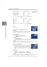
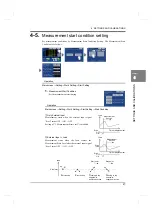
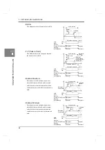
Example) When the section start point is 12mm and Sample Hold is used
* When the section start point and end point are set identically, if the displacement pace is fast, no
load may be held. Set the section start point and end point having a margin in consideration of
the case where the displacement pace is fast.
* In the case of Waveform Reference at Back, where hold operation is performed with the
waveform kept after completion of measurement, the above phenomenon will not occur.
4-6.
Measurement
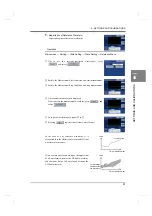
Carry out measurement according to the following procedure on the Main screen.
1.
Check that the status display is “Wait St.” or “Complete.”
If not, check that the Start signal is not input externally, and then press
.
2.
Satisfy the Measurement Start Condition, and start measurement.
When measurement is started, the status display changes to “Sampling.”
* If “Sampling” does not appear, check the following according to the status display.
Wait St.:
The Start signal is not acknowledged. Input the Start signal or press
.
Wait Off:
The Start signal is not OFF. Turn OFF the Start signal.
Wait Lv.:
After the Start signal is input, the load or displacement does not cross
the Measurement Start Level. Change the Measurement Start Level
or change the Start signal input timing.
Complete: Measurement is already stopped. See Step 4 onward.
3.
Satisfy the Measurement Stop Condition, and stop measurement.
Upon completion of measurement, the status display changes to “Complete.”
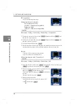
4.
As needed, press
to check the waveform.
Load
Displacement
This data is held
10mm
12mm
14mm
Load sampling: 4000sps (every 250
μ
s)
○
Load sampled by 250
μ
s
●
Load kept in a waveform
16mm
No-sampling section
Not held here
○
Hold point
Resolution
Resolution
Resolution
(2mm)
(2mm)
(2mm)
Status display
Summary of Contents for DeviceNet F381A
Page 1: ...15APR2013REV 3 10 DYNAMIC FORCE PROCESSOR F381A OPERATION MANUAL ...
Page 9: ...Contents VIII Contents VIII M E M O ...
Page 34: ...25 2 INSTALLATION AND CONNECTION 25 INSTALLATION AND CONNECTION Chapter 2 M E M O ...
Page 147: ...138 8 SPECIFICATIONS 138 SPECIFICATIONS Chapter 8 8 2 Outside dimensions Unit mm ...
Page 164: ......


