22
6
EXTERNAL INPUT/OUTPUT SIGNALS
22
EX
TERNAL INPUT/OUTPUT S
IGNAL
S
Chapter
6
6-1.
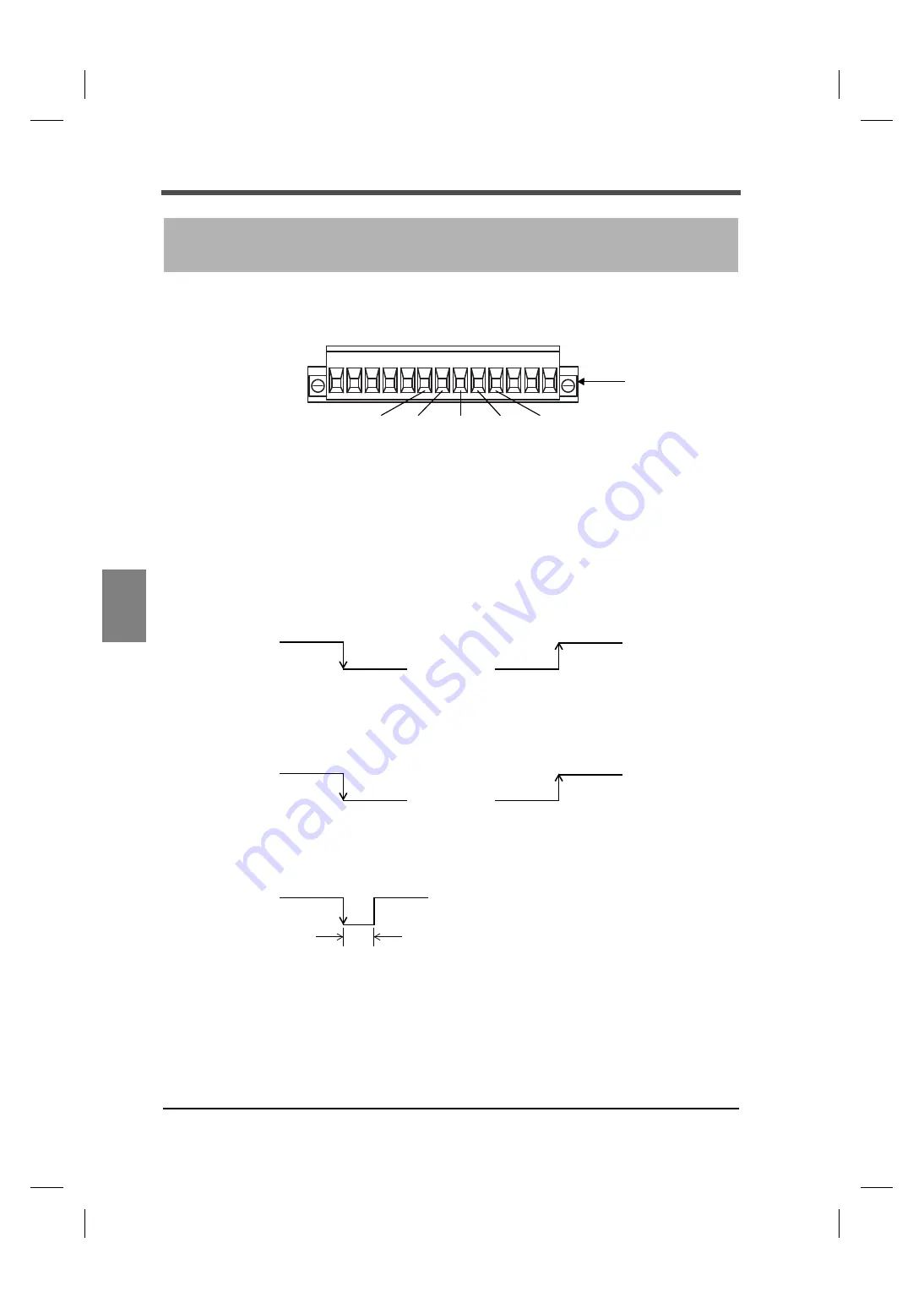
Connector pin assignments
6-2.
External input signals
IN1: Hold/Judge
IN2: Digital zero
■
Hold/Judge <edge input>
For hold signal, please use hold mode.
When the hold mode is OFF, it operates as a judgment signal of comparison timing.
However, it is unrelated when comparison timing condition is ALWAYS or NZ.
■
Digital zero <edge input>
The digital zero works to zero the indicated value.
6
EXTERNAL INPUT/OUTPUT SIGNALS
Signal input/output
6 7 8 9 10
IN1
IN2
OUT1 OUT2
7
8
9
10
COM
6
terminal block
OFF
Hold ON
ON
OFF
Hold OFF
ON
OFF
Judge ON
ON
OFF
Judge OFF
ON
OFF
ON
Pulse width 50mSec or more
Summary of Contents for F331
Page 1: ...OPERATION MANUAL 26MAY2014REV 1 02 DIGITAL INDICATOR F331 ...
Page 79: ...70 8 SPECIFICATIONS 70 SPECIFICATIONS Chapter 8 8 2 Dimensions Unit mm ...
Page 82: ...73 8 SPECIFICATIONS 73 SPECIFICATIONS Chapter 8 When the RS 485 option is equipped Unit mm ...
Page 83: ...74 8 SPECIFICATIONS 74 SPECIFICATIONS Chapter 8 When the RS 232C option is equipped Unit mm ...


