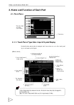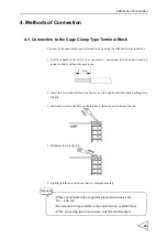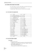
2.Name and Function of Each Part
11
2-2. Rear Panel
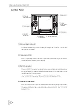
1. AC power input connector
Connect the attached AC power cord. The input voltage is 100 ~ 240V AC (
±
10%), and
the frequency is 50/60Hz.
2. Frame ground (F.G)
This is a grounding terminal. Be sure to ground the FG terminal to prevent electric
shocks and failures caused by static electricity.
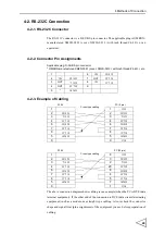
3. RS-232C connector
This is an RS-232C connector to send and receive measured data and status information.
The applicable plug is OMRON-manufactured XM2D-0901 (cover: XM2S-0913 <with
inch thread #4-40>) or an equivalent.
(See "4-2. RS-232C Connection" P24, and "18-2. RS-232C Interface" P133.)
4. Calibration LOCK switch
This is a LOCK switch to prevent calibrated values from being changed by mistake.
Changing of calibrated values is prohibited when this switch is ON. (See "5-5. LOCK
1. AC power
2. Frame ground
3. RS-232C
connector
4. Calibration
5. Control connector
6. SI/F terminal
7. Analog
8. Optional slot
input connector
LOCK switch
input / output
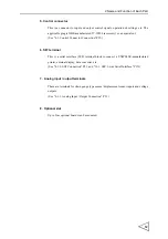
terminals


