background image

14.Waveform Editing

83

14-3. Waveform Sampling

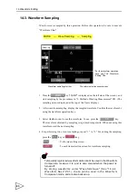
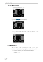
Waveforms are sampled by this operation. Before this operation, be sure to execute

"Waveform Clear".

1.  Press the

key ("SAMP" is displayed on the left side of the screen.), and

start sampling by the procedures in "9. Method of Starting Measurement" P43. (The
sampling status is displayed at the top of the Y-axis display.)

2.   After waveform sampling, display the sampled waveform. Confirm the waveform by

using the waveform operation keys.

3.  Select whether or not to use this waveform. To use, press the 

 key.

The waveform obtained by sampling is registered temporarily. When not using this
waveform, start the next sampling.

4. For performing two or more samplings, repeat "1." to "3." For ending the sampling,

press the 

 key or 

 key. 

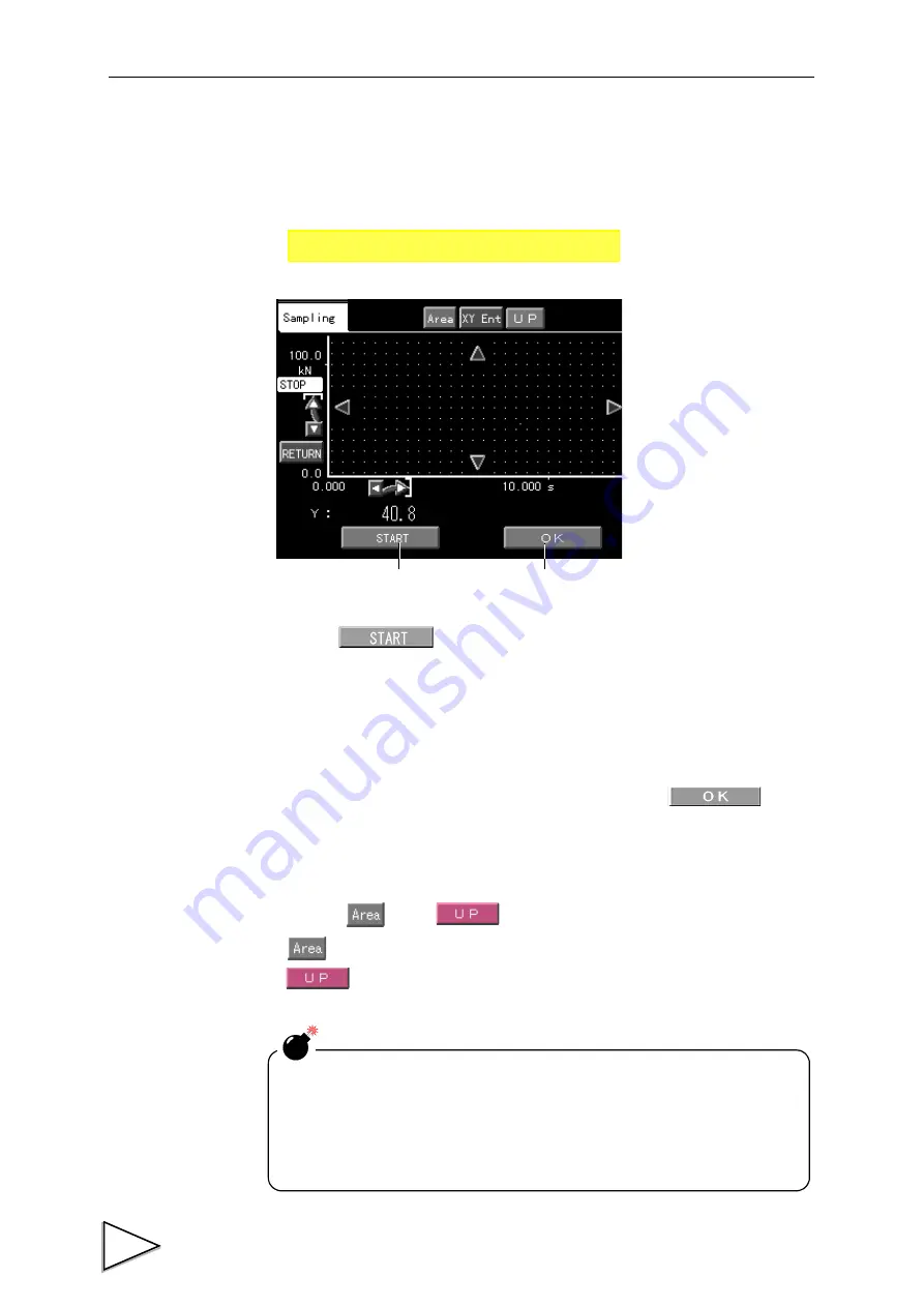
: To the area setting screen.

: To each item selection screen for waveform sampling.


MODE    

    Wave Sampling    

    Sampling

* For the waveform operation

keys, see "14-4. Waveform
Editing" P84.

Waveform sampling start key

Waveform selection execution key

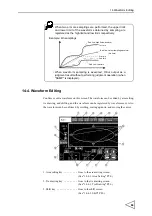
Temporarily registered waveform data cannot be used in the Waveform
Comparison mode as it is, and is also cleared when the power is
turned off.
By storing waveforms under "Waveform Save" (See "14-4-4.
Waveform Save" P91.)
, these can be used in the Waveform
Comparison mode, and are also backed up.

Summary of Contents for f395

Page 1: ...Operation Manual F395 DYNAMIC FORCE PROCESSOR 10 Apr 2012 Rev 1 12...

Page 2: ...your kind purchase of F395 Dinamic Force Processor To take full advantage of high performance of F395 Thoroughly read this operating manual first before use and understand the explanations contained...

Page 3: ...surely follow divide into and and are indicated by the following documents Notes indicated here are the serious contents related safely Please use after understanding the contents well WARNING CAUTIO...

Page 4: ...o ground the protective ground terminal When smoke a nasty smell or strange sound please shut off a power supply immediately and extract a power supply cable Do not install in the following environmen...

Page 5: ...minal block Use shielded cables for the connection of strain gauge type sensor displacement sensor External input and output or options Take adequate shielding measures when using at the following loc...

Page 6: ...ent and human body What is RoHS It is an abbreviation for Restriction on Hazardous Substances which is implemented by the European Union EU The Directive restricts the use of six specific substances i...

Page 7: ...ion Mode at a Glance 5 1 8 Standard Interface 6 1 9 Waveform Reading 6 2 Name and Function of Each Part 7 2 1 Front Pane 7 2 1 1 Touch Panel Type Color Liquid Crystal Display 7 2 2 Rear Panel 11 3 Scr...

Page 8: ...and Output Signals 25 4 3 3 Equivalent Circuit Input 30 4 3 4 Equivalent Circuit Output 30 5 Methods of Calibration 31 5 1 What is Calibration 31 5 2 CH1 Input Calibration and CH2 Input Calibration 3...

Page 9: ...ld 50 10 3 3 Valley Hold 51 10 3 4 P P Peak to Peak Hold 52 10 3 5 Period Specified Hold Peak Valley P P 53 10 3 6 Time Specified Hold Peak Valley P P 54 10 3 7 Time Specified Automatic Hold Peak Vall...

Page 10: ...g in the Waveform Comparison Waveform and Displacement Comparison Mode 76 13 7 Hold Operation 78 13 7 1 Operation and Operating Method 78 13 7 2 Setting Method 80 13 8 Un passing Area Output 80 13 9 D...

Page 11: ...of Setting the Operation ch 100 16 2 Each Setting Item 103 16 2 1 Channel Number Selection 103 16 2 2 Parameter Copy 104 16 2 3 Select Analog CH 104 16 2 4 Hold Setting 105 16 2 5 Auto Code Up Code U...

Page 12: ...Detection Interval A 125 16 3 7 Slope Detection Interval B 125 16 3 8 Preliminary Slope Detection Point 126 16 3 9 Hysteresis Interval 126 17 System related Settings and Operations 127 17 1 Set Value...

Page 13: ...d Waveform 143 18 4 7 Reading the Effective Area of The Sampled Waveformend of the Area 144 18 4 8 List of Accessible Waveforms by Operation Mode 145 18 4 9 Reading Indicated Values Status 146 18 4 10...

Page 14: ...ternal Power Supply Shared with Excitation Voltage 158 23 7 Interface 158 23 8 General Performance 159 23 9 Option 159 23 10 Accessories 160 24 Setting Items list 161 25 Statement of Conformation to E...

Page 15: ...g This Instruction Manual Since various names on the F395 are determined by assuming the X axis sensor displacement input matters relating to the X axis input may be expressed as displacement dependin...

Page 16: ...form Comparison Waveform and Displacement Comparison functions cannot be used simultaneously Carefully read the explanations of 7 Measurement Operation Functional Settings P40 10 Multi Hold Mode P47 1...

Page 17: ...1 3 Multi Hold Procedures In the Multi Hold mode necessary points are detected in the displayed waveform to make a judgment such as a High Low Limit Comparison Up to 32 channels of Hold types High and...

Page 18: ...to control externally See 4 3 Control Connector Connection P25 5 Input T H and H M signals in accordance with the selected hold function and check to see if operation is performed as set See 10 3 Hol...

Page 19: ...2 Waveform Drawing Procedures P3 2 Carry out Waveform Comparison Waveform and Displacement Comparison settings See 13 2 Setting and Operating Method P68 3 Select the channel number s you want to contr...

Page 20: ...o external equipment such as a printer and large display manufactured by us can be used by using the SI F 2 wire serial interface See 18 1 SI F 2 wire Serial Interface P132 1 9 Waveform Reading Measur...

Page 21: ...gh and Low Limit 5 Lithium battery 6 Status display 3 X axis displacement 4 Displacement High and Main screen 1 Y axis display Performs Digital Zero 7 Set Operation 8 Control Signal 9 Display of In th...

Page 22: ...h operation ch set by external input in the Multi Hold Hysteresis mode Displays the HI HI Limit LO LO Limit of the ch operation ch set by external input in the Waveform Comparison Waveform and Displac...

Page 23: ...ode Displacement High Limit Displacement Low Limit Displacement Hold High Limit Displacement Hold Low Limit P110 5 Lithium battery alarm Displayed when the lithium battery requires replacement Normall...

Page 24: ...ison waveform of the currently set opera tion ch in the Waveform Comparison Waveform and Displacement Comparison mode See 13 1 Function P68 Operation mode Status display Multi Hold Hysteresis Hysteres...

Page 25: ...d receive measured data and status information The applicable plug is OMRON manufactured XM2D 0901 cover XM2S 0913 with inch thread 4 40 or an equivalent See 4 2 RS 232C Connection P24 and 18 2 RS 232...

Page 26: ...P25 6 SI F terminal This is a serial interface SI F terminal block to connect a UNIPULSE manufactured printer external display data converter etc See 4 1 2 SI F Connection P23 and 18 1 SI F 2 wire Se...

Page 27: ...hart Main Mode Setting Special Numerical Value Input Selection Each mode key Execution Set Value Selection Hold Point Display or Waveform Waveform Sampling Reading Sampling Waveform Reading Waveform E...

Page 28: ...ading Hold Point for Rejected Waveform Rejected Waveform Basic Setting Code Setting Hold Setting key Judgment Setting Hold Setting Category key Waveform Reading Graph Reading Selection Reading Graph E...

Page 29: ...d Wave PAGE1 Read Wave P92 Read NG Wave P96 NG Wave CLR P97 Control Signal P99 Y StartPoint P97 Y Scale P97 X StartPoint P98 X Scale P98 Communication PAGE1 Speed P133 Data Length P134 Parity P134 Ter...

Page 30: ...0 F T Output P120 Basic PAGE1 Parameter Copy P104 Select CH P104 Lv Axis Select P113 Wave Start Level P113 Wave End Level P113 Inhibit Timer P119 Hys Interval P119 F T Limit P120 F T Output P120 PAGE2...

Page 31: ...od of specifying a setting item is described as follows Example Specifying the Displacement Hold High Limit in the Hysteresis mode This operation can be performed by the following procedures 1 Press o...

Page 32: ...Press and select the setting item DPM Hold HI in this case 3 3 2 Unit Setting Method In this manual the method of setting an item with multiple selections is described as follows Example Setting a uni...

Page 33: ...ing screen appears Select a desired item by pressing the and keys Check that the desired description is displayed at the top and press OK for entry Mode Set Channel number selection in code setting is...

Page 34: ...not become loose 2 Insert the screwdriver firmly into the hole on the right hand side while pushing it up slightly 3 Insert the wire into the hole on the left hand side so as not to loosen the end 4...

Page 35: ...t outputs voltage proportional to sensor input The voltage output is approx 2V per 1mV V sensor input and the load resistance is 5k or more 9 GND GND terminal for the V OUT terminal Common to pin 6 an...

Page 36: ...and S For connecting a sensor be sure to use shielded lines and separate wiring from lines with heavy noise such as wiring of power equipment and wiring of digital equipment and AC lines The analog G...

Page 37: ...2 0V Voltage 5V Approx 5 6V Current 20mA Approx 5 2V 4 1 2 SI F Connection This is a 2 wire serial interface to connect a UNIPULSE manufactured printer external display etc Up to three nonpolarized e...

Page 38: ...s DTE data terminal equipment If the other end of the connection is DCE data circuit terminating equipment such as a modem use straight type cabling Also recheck the connector shape and signal lines p...

Page 39: ...value is cancelled when the next sampling starts 1 COM 26 COM 2 IN Display after measurement 27 IN D Z 3 IN Capture start by external signal 28 IN T H 4 IN Operation by waveform termination level 29...

Page 40: ...light is lit when this signal is ON If it is kept ON the backlight will not go out Select HH LL Selects operation of HH LL output pin 20 When this signal is OFF Result of judgment on the currently set...

Page 41: ...displacement 2 Judgment output signals The results of High Low Limit Judgment in each Operation Mode are output LO1 OK1 HI1 1 When the Multi Hold Hysteresis mode is used Outputs the results of judgme...

Page 42: ...START signal is turned ON 2 When the Hysteresis 2 mode is used Outputs the accumulated 1 results of judgment of LO1 OK1 and HI1 with the timing of inputting HOLD1 HOLD2 and HOLD3 Outputs the accumula...

Page 43: ...ison Waveform and Displacement Comparison Mode P76 WARNING This signal is output when displacement input is used and sampling is thinned out See 13 5 Waveform and Displacement Comparison Mode P74 Hyst...

Page 44: ...ircuit External elements should pass Ic 10mA or more Leaks of external elements should be 100 A or less The external input circuit is minus common A circuit of source type cannot be connected 6mA Appr...

Page 45: ...cement to the sensor and inputting the actual load displacement by keypad Accurate calibration with few errors can be performed 5 2 CH1 Input Calibration and CH2 Input Calibration Perform calibration...

Page 46: ...on is voltage current Turn off the power and connect the sensor Set the Unit to be used Set the Decimal Place Set the minimum value of the digital changes Set the initial zero point Set the rated outp...

Page 47: ...n is voltage current Turn off the power and connect the sensor Set the Unit to be used Set the Decimal Place Set the minimum value of the digital changes Set the initial zero point Set the span gain p...

Page 48: ...All Unprotect Software lock Now the locks are released Upon completion of calibration hardware lock and software lock again to prevent misoperation 5 6 Excitation Voltage Set the voltage value to be a...

Page 49: ...es Setting range 1 100 Not including the decimal point 5 9 Decimal Place Set the decimal place Setting item 0 0 0 0 00 0 000 5 10 Zero Calibration Set the initial zero point 1 Bring the sensor into a...

Page 50: ...ng range 9 999 0 100 0 100 9 999 Load Setting range 100 9999 Not including the decimal point iii Current output sensor Sensor Output mA Setting range 99 99 1 00 1 00 99 99 Load Setting range 100 9999...

Page 51: ...CH2 Calibration cannot be performed with the same input value as zero calibration The full scale value of displacement is determined by the value input for the Load item of Equivalent Input Calibrati...

Page 52: ...cutoff frequency of the low pass filter can be selected from the following With increasing cutoff frequency the response becomes fast but noise components may be displayed in a waveform Setting item 1...

Page 53: ...tion setting is either CAL Protect or All Protect or the LOCK switch on the rear panel is ON Also the displacement input value cannot be zeroed by the above methods It is automatically zeroed when sam...

Page 54: ...pling rate is automatically changed to 2kHz At the same time the buzzer beeps 7 2 Sampling Rate Select the sensor signal reading speed from the following Setting item 4 kHz 2 kHz 1 kHz 500 Hz 200 Hz 1...

Page 55: ...etting cannot be changed by this item About advance waveform display When the operation mode is Multi Hold or Waveform Comparison a waveform is displayed gradually without waiting for completion of ta...

Page 56: ...screen according to the measuring conditions 1 If any result is an error the whole column becomes red 2 If there is no result is displayed 3 The results of comparison are displayed H L HH or LL is di...

Page 57: ...TOP signal turns ON or when 2048 point sampling is exceeded or when the input signal crosses over the Waveform Termination Level with the signal Waveform termination level operation ON The relationshi...

Page 58: ...is cleared when the STOP signal is turned on with the START signal ON Therefore waveform capturing will not start until the level edge at B is established Waveform capturing starts at A if the STOP si...

Page 59: ...uring finally starts at E Example 5 If the signal Capture start by external signal is ON when the START signal turns from ON to OFF waveform capturing starts immediately irrespective of whether or not...

Page 60: ...the status is shifted as follows 1 If the waveform has already crossed over the sampling start level the level edge is cancelled by the first STOP signal and the status is shifted to STOP status samp...

Page 61: ...mark 10 2 Setting and Operating Method 1 Set desired value s 0 31 32 all channel number selection under Channel Number Selection in Code Setting and set each item such as the High and Low Limits 2 Inp...

Page 62: ...ned Switching operation channels during sampling will result in the following operation 1 Data of the Judgment output signal LO1 OK1 HI1 will be accumulated and output by LO2 OK2 HI2 2 The judgment op...

Page 63: ...input and the instant when the indicated value is held Ts 0 8msec max t2 Delay time between the instant when the T H signal is cancelled and the instant when the indicated value returns to tracking Ts...

Page 64: ...e indicated value returns to tracking Ts 0 8msec max t2 t T H COMPLETE t1 t2 t1 Note During the indeterminate period the Judgment output varies with variations in the input waveform However the COMPLE...

Page 65: ...value returns to tracking Ts 0 8msec max t2 t T H COMPLETE t1 t2 t1 OFF ON OFF ON OFF ON Sensor input value Detection hold period Detection hold period Indicated value Indeterminate period Note Indet...

Page 66: ...lue 0 OFF ON OFF ON OFF ON COMPLETE Indicated value Sensor input value Detection hold period Indeterminate period Note Reference line Indicated value 0 Here is referenced only for the hold period Note...

Page 67: ...when the H M signal is input and the instant when the hold is detected Ts 0 8msec max t2 Delay time between the instant when the H M signal is cancelled and the instant when the hold is determined Ts...

Page 68: ...he instant when the H M signal is input and the instant when the hold is detected Ts 0 8msec max t2 Delay time between the instant when the hold detect time expires and the instant when the hold is de...

Page 69: ...me between the instant when the indicated value exceeds the hold start level and the instant when the hold is detected Ts msec max t2 Delay time between the instant when the hold detect time expires a...

Page 70: ...ue exceeds the hold start level and the instant when the hold is detected Ts msec max t2 Delay time between the instant when the H M signal is input and the instant when it is detected that the indica...

Page 71: ...by the method in 16 2 12 Minimum Slope Detection Value Slope Detection Interval A Slope Detection Interval B Preliminary Slope Detection Point P118 Point a is held as an inflection point when the amou...

Page 72: ...hold is determined Ts 0 8msec max t4 Delay time between the instant when the T H signal is input and the instant when the indicated value returns to tracking Ts 0 8msec max t4 t H M t2 t1 Hold Start...

Page 73: ...hold is determined Ts 0 8msec max t4 Delay time between the instant when the T H signal is input and the instant when the indicated value returns to tracking Ts 0 8msec max t4 t H M t2 t1 OFF ON OFF...

Page 74: ...hold is determined Ts 0 8msec max t4 Delay time between the instant when the T H signal is input and the instant when the indicated value returns to tracking Ts 0 8msec max t4 t H M t2 t1 OFF ON OFF...

Page 75: ...hold is determined Ts 0 8msec max t4 Delay time between the instant when the T H signal is input and the instant when the indicated value returns to tracking Ts 0 8msec max t4 t H M t2 t1 OFF ON OFF...

Page 76: ...e second time onward are ineffective t1 Delay time between the instant when the T H signal is input and the instant when detection starts Ts 0 8msec max t2 Delay time between the instant when the T H...

Page 77: ...og CH setting for operation ch 1 operation ch 2 is ineffective For the High Low Limit Judgment output the result of judgment of the latest input pulse is output to LO1 OK1 HI1 and the results of judgm...

Page 78: ...of the X axis and handling of sudden changes in displacement input are the same as those in the Waveform and Displacement Comparison mode See 13 5 Waveform and Displacement Comparison Mode P74 4 Go a...

Page 79: ...mparison Uses the HI HI Limit LO LO Limit See 16 2 7 High Limit Low Limit HI HI LO LO Mode HI HI Limit LO LO Limit P109 3 Pulse Input Determine displacement points by the ON edges of HOLD 1 3 See 4 3...

Page 80: ...sult of comparison is an error the result of measurement is displayed in red The results of measurement are displayed from the left in the order of pulse input When no pulse is input the result of mea...

Page 81: ...g for operation ch 1 operation ch 2 is ineffective Do not input any pulse within the hysteresis interval because the result is not judged normally No judgment is made if no pulse is input during go A...

Page 82: ...See 7 4 X Y axis Setting by Operation Mode and Input CH P41 Level Axis Select Y axis is fixed in the Waveform Comparison mode See 16 2 9 Level Axis Select Waveform Start Level Waveform Termination Lev...

Page 83: ...form Sampling Procedures Waveform sampling can be performed efficiently by the following procedures It is assumed that the F395 has been calibrated For the setting operating method of each function se...

Page 84: ...lue close to zero approx the increment 10 Set a slightly larger value if noise is large 4 Set desired channel s with external channel selection signals 5 Exit the setting menu go to the main screen in...

Page 85: ...ength of one cycle of the waveform sec The frequency obtained by this expression is the most suitable sampling rate When the above waveform is taken for example 2000 6 sec 333 33Hz The closest value u...

Page 86: ...sary Set the point under Waveform Editing and rewrite the graph under Select Edit High and low limits can be set for the waveform within the specified range in a unit of or indicated value and a new w...

Page 87: ...d mark display will result Up to 16 pairs ch of High and Low Limit Waveforms can be stored which can be switched and controlled by external selection signals as desired When the results of measurement...

Page 88: ...ve cannot be displayed The internal resolution is approx 1 2000 Also displacement input values are automatically digital zeroed with a sampling start under CAL Protect when the Level Axis Select setti...

Page 89: ...measured by peak hold Therefore even if the displacement is restored the measured value of the peak point of displacement is processed Displacement values are measured by valley hold during return mea...

Page 90: ...ween the instant when the START signal is input and the instant when the comparison starts Ts 0 8msec max t3 Minimum START signal width Ts 0 8msec min t4 Standby time to start the next comparison Appr...

Page 91: ...een the instant when the START signal is input and the instant when the judgment output and COMPLETE change Ts 1 6msec max t7 Delay time between the instant when the comparison ends and the instant wh...

Page 92: ...LO LO Mode HI HI Limit LO LO Limit P109 is Hold If the setting is Sampling Value real time judgments on the sampling value will result START T H STOP COMPLETE OFF ON OFF ON OFF ON OFF ON For the delay...

Page 93: ...OK2 HI2 For hold operation and judgment of the hold point the inhibit timer is effective COMPLETE is output with respect to Waveform Comparison Waveform and Displacement Comparison Therefore check th...

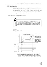
Page 94: ...O Limit will result 4 For High Low Limit Judgment of the hold point set the HI HI Limit LO LO Limit See 16 2 7 High Limit Low Limit HI HI LO LO Mode HI HI Limit LO LO Limit P109 13 8 Un passing Area O...

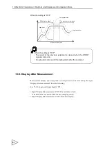
Page 95: ...ay after measurement ON The last value is held The held value is canceled when the next sampling starts 2 Input Display after measurement OFF Real time display When the setting is OFF The result of th...

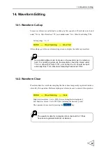
Page 96: ...peration Before sampling waveforms be sure to execute this operation MODE Wave Sampling Wave Call No pass fail judgment can be made on the waveform as it is called up here For making a judgment the wa...

Page 97: ...y The waveform obtained by sampling is registered temporarily When not using this waveform start the next sampling 4 For performing two or more samplings repeat 1 to 3 For ending the sampling press th...

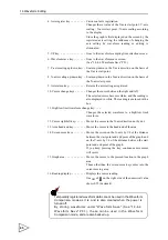
Page 98: ...Tie drawing key Goes to the tie drawing screen See 14 4 1 Tie Drawing P86 3 Shift key Goes to the shift screen See 14 4 2 Shift P89 When two or more samplings are performed the upper limit and lower l...

Page 99: ...ed in white The reading is enclosed with a box 11 High low limit waveform change key Changes the selected waveform to a high low limit waveform 12 Cursor right left key Moves the cursor in the X axis...

Page 100: ...display or help display 3 Character display area Displays the reading or help Reading display Displays the ongoing point in white Displays the previous point in blue Help display Gives a brief descrip...

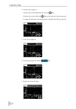
Page 101: ...ed by pressing the key The point can be moved with the key on the right side of the previous point To prepare the next point touch the graph area on the right side of the present point 3 A new point i...

Page 102: ...3rd point Points from the 3rd point onward are deleted and a new 3rd point is prepared 14 4 1 3 About the Help Function A brief description of the operating procedure is given by pressing the key 1 H...

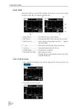
Page 103: ...ct key Selects the digit to input a numerical value _ indicates the selected digit 4 key Increases decreases the value of the selected digit 5 Clear key Resets the numerical value back to zero 6 Readi...

Page 104: ...the simple numerical input section the waveform can be shifted while specifying the amount of increment decrement After completion of shifting press the key 4 Display the shifted waveform 14 4 3 Area...

Page 105: ...ted by a blue line at the top of the screen and outside the area becomes gray 14 4 4 Waveform Save Waveforms edited under Waveform Editing are stored by this operation Waveforms saved here are used fo...

Page 106: ...ch point of the waveform sampled and displayed by the F395 can be read 1 Cursor center key Moves the screen so that the cursor position comes at the center of the screen If the cursor is positioned ne...

Page 107: ...Limit Waveforms are not available In the High Low Relative mode if Y axis High and Low Limits exceed 10000 HI and LO are displayed respectively In the Hysteresis Hysteresis 2 Waveform and Displacement...

Page 108: ...screen traces the waveform 15 1 2 Waveform Reading in the Hysteresis Hysteresis 2 Mode Select the go return waveform in the Hysteresis Hysteresis 2 mode with the key Go waveform In the Hysteresis 2 m...

Page 109: ...rsor indicated point Displays HI HI and LO LO Limits on the measurement ch at the cursor indicated point 15 1 4 Hold Jump Function Hold Points are quickly searched for by this function Every time the...

Page 110: ...veform Reading screen 15 2 Rejected Waveform Reading Rejected Waveforms having failed in sampling are read by this operation Up to four waveforms can be stored Setting item Cancel Last Wave 2nd Last W...

Page 111: ...aling Set the Y axis scale of the graph Select scaling so that the input waveform is properly displayed Setting item 100 50 20 10 5 2 1 Up to the 2nd Last Wave are stored in the Hysteresis mode NG wav...

Page 112: ...tion for PUI 15 7 X axis Scaling Set the X axis scale of the graph Select scaling so that the input waveform is properly displayed Setting item 100 50 20 10 Multi Hold Waveform Comparison mode Hystere...

Page 113: ...he screen Setting item ON OFF Display is provided when the Control Signal Display setting is ON MODE Read Wave Control Signal T H pink H M green In modes other than the Hysteresis Hysteresis 2 mode Go...

Page 114: ...son Waveform and Displacement Comparison mode the operation ch of 16 or more is totally processed as 15ch The operation ch is taken in by double reading For avoiding the delay at change time use the S...

Page 115: ...the operation ch by external input is ineffective When the Hysteresis mode is set it functions only when X axis measured value 10000 After completion of sampling the operation ch is fixed at the last...

Page 116: ...line with the example of setting below Example CODE No 0 1 2 3 4 Auto Code Up ON ON ON ON OFF Code Up Point 10 0mm 20 0mm 999 9mm 40 0mm 20 0mm When the Hysteresis 2 mode is set if the Auto Code Up is...

Page 117: ...e switched and controlled as desired externally Setting range 0 32 Example Setting the operation ch to 5ch 1 Press five times 2 Determine by pressing 32 channels from 0ch to 31ch can be set For settin...

Page 118: ...All items set in Code Setting can be copied 16 2 3 Select Analog CH Set the analog input CH used on the Y axis Setting item CH1 CH2 The setting is limited depending on the set Operation Mode See 7 4...

Page 119: ...Setting item None Sample Hold Peak Hold Valley Hold For details of each hold see 10 3 Hold Functions P48 Example Changing the hold to Inflection Point Hold A in the Multi Hold mode 1 Press None All Se...

Page 120: ...ng vary depending on the category of the hold selected in 2 Hold Set None All Section Period Time Hold Timer P B P P Hold Start Level Minimum Slope Interval A Interval B Pre Point Time Auto Relative I...

Page 121: ...Code Up Point For details of the Auto Code Up mode see 2 Setting by the auto code up function in 16 1 Method of Setting the Operation ch P100 Auto Code Up Setting item ON OFF Code Up Point Setting ra...

Page 122: ...e with High Limit 100 Low Limit 50 When the operation ch 1 since the hold 75 on ch 0 high low limit judgments are made with High Limit 100 75 175 Low Limit 50 75 125 When the operation ch 2 since the...

Page 123: ...ve to the indicated value Hold Value or sensor input value Sampling Value can be set on HI HI and LO LO Limits under HI HI LO LO Mode Also the set values of High and Low Limits on the operation ch in...

Page 124: ...on Value the Set Value of HI HI Limit The HI HI Limit LO LO Limit setting is used for difference judgment in the Hysteresis 2 mode See 12 1 Function P65 Also it is used for High Low Limit Judgment of...

Page 125: ...ement Hold Low Limit Setting range 0 9999 Not including the decimal point In the Hysteresis Hysteresis 2 mode In the Waveform and Displacement Comparison mode MODE Code Set Judgment PAGE DPM Hold HI D...

Page 126: ...connector pin 6 If it is kept ON real time High Low Limit Judgments on the displacement input value will result Also this output has no connection with the COMPLETE signal 3 Both The results of judgme...

Page 127: ...ecified Automatic Peak Hold Inflection Point Hold D Whether to execute the Waveform Start Level Waveform Termination Level with respect to the Y axis or X axis can be set under Level Axis Select Howev...

Page 128: ...son mode the setting is automatically changed to Y axis X axis cannot be set in the Multi Hold Waveform Comparison mode When the Level Axis Select setting is changed from Y axis to X axis if a negativ...

Page 129: ...Setting range 9999 9999 16 2 10 Hold Detect Time This is displayed only when Time Specified Time Specified Automatic is selected in Hold Setting to set the time of hold period Setting range 1 9999 Th...

Page 130: ...ed settings Set referring to the following principles of operation only in cases where holding is unsuccessful or finer adjustments are needed Relative maximum and relative minimum values are detected...

Page 131: ...o or more relative maximum and relative minimum values appear in the waveform the relative maximum and relative minimum values are held according to the Peak and Valley Ordinal setting For example if...

Page 132: ...from the amount of change of the indicated value in Slope Detection Interval B point a is held as an inflection point when the amount of change D exceeds the set Minimum Slope Detection Value Normally...

Page 133: ...sis Interval Set the return value of the displacement input to make a return waveform when the Hysteresis Hysteresis 2 mode is used Setting range 0 9999 0 A return waveform is made when the sampling v...

Page 134: ...orced termination time by a displacement stop Setting item ON OFF In the Waveform and Displacement Comparison Hysteresis 2 mode In the Hysteresis mode 16 2 17 Un passing Area Output Set whether or not...

Page 135: ...raphic display does not appear If graph confirmation is needed set after changing the mode temporarily Items the graphic display of which is determined by the Operation Mode are shown according to the...

Page 136: ...imit HI HI Limit Low Limit LO LO Limit Displacement High Limit Displacement Low Limit Displacement Hold High Limit Displacement Hold Low Limit Waveform Start Level Waveform Termination Level Hold Star...

Page 137: ...ing the center of the graph as the midpoint 16 3 3 Peak and Valley Detection Rate Waveform by the present value of the Minimum Peak and Valley Difference light blue Green Red Green Red Green Red Green...

Page 138: ...Detection Value Displays the relationship to the present value of Slope Detection Interval A Slope Detection Interval B Not changes by the set value but a dummy waveform Red Green Green Red Reference...

Page 139: ...al B Displays the relationship to the present value of Minimum Slope Detection Value Slope Detection Interval A Reference line blue Green Red Green Red Slope Detection Interval A Changes with the pres...

Page 140: ...tion Interval B 16 3 9 Hysteresis Interval Reference line blue Green Red Minimum Slope Changes with the present value of Slope Detection Interval B light blue Detection Value Changes with the present...

Page 141: ...he items applicable to Calibration see 24 Setting Items list P161 The DZ Digital Zero function can be used All Protect Calibration cannot be performed and also set values cannot be changed The DZ Digi...

Page 142: ...can be executed only when the Set Value Protection setting is All Unprotect 17 6 Self test The operating conditions of the F395 body are tested by this function If there is any problem ask your deale...

Page 143: ...klight Press and the backlight goes out Turns Off After that the backlight lights turns on when any place on the screen is touched Contrast Press and the display becomes brighter Press and the display...

Page 144: ...er of 17 24 and 42 49 3 The condition of each input pin is displayed in hexadecimal The relationship between displays and input pins is as follows When the PUI option is mounted the input pulse freque...

Page 145: ...NOVRAM CHK The NOV RAM is tested Approx 15 seconds after execution of the test OK NG judgment is displayed in the blank on the right hand side During testing now NOVRAM chk is displayed At this time n...

Page 146: ...r cable is used the transmitting distance is approximately 300m 328yds Connection Connections with external equipment manufactured by us are non polar and up to three units can be connected in paralle...

Page 147: ...Parity bit None odd or even selectable Code ASCII Connector Pin Assignments 18 3 Interface related Settings Set in agreement with the RS 232C port of the PC sequencer etc to be connected and this dev...

Page 148: ...tomatic Transmission Mode P149 Setting item Normal Continuity Hold Point 18 3 6 SI F Hold Point Transmission Set whether or not to output hold data by SI F automatic printing after completion of sampl...

Page 149: ...1 9 Minimum Slope W 1 7 SP Terminator 0001 9999 Interval A W 1 8 SP 0 Terminator 010 200 Interval B W 1 9 SP 0 Terminator 010 200 Pre Point W 2 0 SP 0 0 Terminator 00 10 Inhibit Timer W 2 1 SP Termin...

Page 150: ...Channel Number Selection changed by the W01 command is exclusive to RS 232C communication The Channel Number Selection of the main body is not changed Request Select CH 0 1 CH 1 2 CH Hold 0 None 1 Sa...

Page 151: ...e Up 0 ON 1 OFF HI LO Relative 0 ON 1 OFF DPM HI LO Mode 0 Hold Value 1 Peak Value 2 Both U Area Output 0 ON 1 OFF Host F395 Terminator Host F395 Terminator Terminator Terminator Return at a normal en...

Page 152: ...alities Something other than SP comes at the place where SP should come Something other than numbers comes at the place where numbers should come The value exceeds the setting range If SP comes at the...

Page 153: ...d for measurement 92 High Low Limit Waveform obtained by waveform sampling Other values Do not use Host F395 Terminator Terminator Input a set value out of the following table Present set value Return...

Page 154: ...the operation is executable only when the set value of W51 is 0 15 or 92 In the Waveform Comparison mode and Waveform and Displacement Comparison mode the operation is executable only when the set val...

Page 155: ...nts As a result data can be handled without handling such signs Generally the method by which a fixed offset is given to all elements in notation is called offset binary The F395 adds 32768 8000H in h...

Page 156: ...As for the 6th character on the host side 0 specifies a go waveform and 1 specifies a return waveform when the set value of W51 is 80 81 or 90 in the Hysteresis mode In other modes 0 specifies a low...

Page 157: ...ti Hold mode and Hysteresis mode the operation is executable only when the set value of W51 is 0 15 or 92 In the Waveform Comparison mode and Waveform and Displacement Comparison mode the operation is...

Page 158: ...ctive waveform area 0000 2047 In the Multi Hold mode the operation is executable when the set value of W51 is 0 15 80 83 90 or 92 In the Hysteresis mode the operation is executable when the set value...

Page 159: ...W51 set value Waveform data writing W52 Waveform data reading W52 Area writing W54 55 Area reading W54 55 Registered waveforms for comparison Specify channel No 0 15 Last Rejected Waveform 80 2nd Las...

Page 160: ...atest sampled waveform update 0 OFF 1 ON Low Limit exceeded 0 Low Limit or less 1 Low Limit exceeded 2 LO LO Limit exceeded The status priority is as follows HI HI Limit exceeded High Limit exceeded H...

Page 161: ...ulse 2 22 Pulse 3 30 Waveform Comparison NG point SY SX SUM 1 4 The last two bytes of the total of all ASCII data from RHG to SX of 9 expressed as a 4 digit hexadecimal number 1 All reading Latest sam...

Page 162: ...cted waveform Y axis data X axis data Status Hold type F395 R H G 1 SY SX Terminator Host R H G Terminator Entry of a numerical value from 1 to 9 into allows reading of the th hold data Y axis data X...

Page 163: ...these two modes no set values can be read or written through the RS 232C 2 Hold point mode The following are transmitted upon completion of sampling The RHGA command is automatically output through t...

Page 164: ...axis 9999 OVER shows that display of a value out of the range in the positive direction has been attempted and OVER shows that display of a value out of the range in the negative direction has been a...

Page 165: ...ase of strain gauge inputShort circuit between the three points of SIG SIG and EXC iii In the case of voltage current input Short circuit between the two points of SIG and SIG Checking method When the...

Page 166: ...XC EXC SIG SIG F G FRAME CPU CPU Lithium battery Buzzer Control Control 24 IN 16 OUT PULSE IN D A OUT SUB CPU CPU MAIN CPU COLOR LCD LCD CONTROLER DRAM 1Mbyte FLASH 1Mbyte MEMORY NOV RAM NOV RAM SRAM...

Page 167: ...21 Outer Dimensions 153 21 Outer Dimensions Unit mm 3 3 5 5 Rear Front Side Panel cut dimensions...

Page 168: ...e F395 to a panel according to the following procedures 1 Remove the rails on both sides 2 Make a hole according to the panel cut dimensions 3 Mount the F395 and fix with the side rails 165mm 130mm Pa...

Page 169: ...tion Equivalent input calibration range 3 0mV V 0 5mV V 0 5mV V 3 0mV V Equivalent input calibration range error Within 0 2 F S Accuracy Non linearity Within 0 02 F S 1 digit at 3 0mV V input Zero dri...

Page 170: ...00 times sec max when one input is used 2000 times sec max X axis measurement when two inputs are used Changeable to 100 200 500 1000 2000 times sec according to the input waveform Resolution Approx 1...

Page 171: ...le sensor The specifications of the sensor connectable to this option are as follows Output Incremental type two phase output A and B signal output Also adaptable to one phase output The A phaseinput...

Page 172: ...en collector output Emitter COM terminal Output ON with transistor ON Analog output Approx 2V relative to 1mV V load cell input Approx 5 6V relative to 5V voltage input Approx 5 2V relative to 20mA cu...

Page 173: ...ng conditions Temperature Operating temperature range 0 40 non condensing Storage temperature range 20 60 non condensing Humidity 85 RH or less non condensing Outer dimensions 174W 156D 135H mm Not in...

Page 174: ...00 1 Connector for Pulse input 57 30140 with PUI option 1 Connector for CC Link option 721 105 037 000 with the CC Link option 1 Connector for DeviceNet option MSTBP2 5 5 STF 5 08AU with DeviceNet opt...

Page 175: ...Operation Mode Multi hold 0 Multi hold 1 Wave Comp 2 Hysteresis 3 Wave Displace 4 Hysteresis 2 Sample Rate 1kHz 0 4k 1 2k 2 1k 3 500 4 200 5 100 Code Set 0 31 ch Ch No 0 2 digits 0 will result when t...

Page 176: ...trol Signal ON 0 ON 1 OFF Y StartPoint 0 0 4 digits sign Y Scale 10 0 100 1 50 2 20 3 10 4 5 5 2 6 1 X StartPoint 0 000 4 digits X Scale 10 0 100 1 50 2 20 3 10 Communication Speed 19200bps 0 1200 1 2...

Page 177: ...V Please use the power cable authorized in the country when you use this product outside Japan 3 Use shielded cable for connection with components other than power supply such as sensor input output s...

Page 178: ...ing surge protect No lightning surge protector MAINTRAB MNT 1D is included as a standard It is optionally available TSU02 in combination with a 250V AC high voltage cable in EU outlet form See below S...

Page 179: ...te core sensor cable and cable for power supply output It is necessary to attach the ferrite core to the sensor cable and cable for power supply output F395 load cell Fasten tightly to the cable with...

Page 180: ...Unipulse Corporation 9 11 Nihonbashi Hisamatsucho Chuo ku Tokyo 103 0005 Tel 81 3 3639 6120 Fax 81 3 3639 6130...

Reviews: