4.Methods of Connection
25
4-3. Control Connector Connection
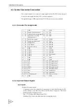
The control connector is a connector to input signals to allow the F395 to function, and
to output control signals from the F395 to external equipment.
The applicable plug is DDK-manufactured 57-30500 (accessory) or an equivalent.
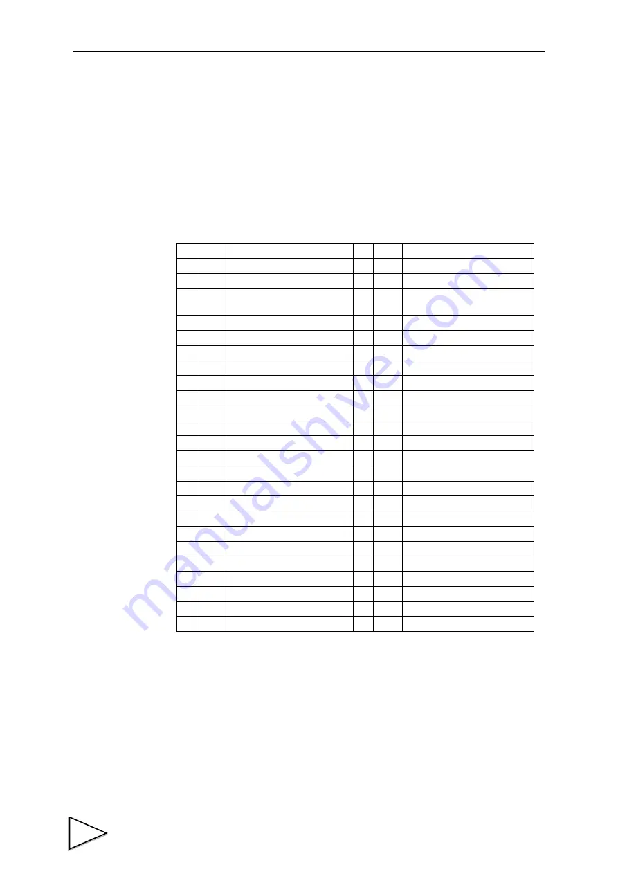
4-3-1. Connector Pin Assignments
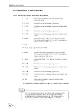
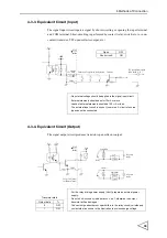
4-3-2. Input and Output Signals
Input signals
・
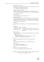
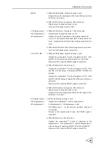
Display after measurement:
A measured value at the completion of measurement is held when this signal is ON,
and the holding is cancelled when OFF in the Waveform Comparison / Waveform
and Displacement Comparison mode.
(See "13-9. Display After Measurement" P81.)
[Holding of the value is cancelled when the next sampling starts.]
1
*
COM
26
*
COM
2
IN
Display after measurement
27
IN
D/Z
3
IN
Capture start by external signal 28
IN
T/H
4
IN
Operation by waveform
termination level
29
IN
H/M
5
IN
Prohibit touch panel
30
IN
START
6
IN
Displacement hold cancel
31
IN
STOP
7
IN
Backlight ON
32
IN
HOLD1
8
IN
Select HH/LL
33
IN
HOLD2
9
IN
Reset auto code up
34
IN
HOLD3
10
*
COM
35
*
COM
11
IN
CODE1
36
IN
CODE16
12
IN
CODE2
37
IN
STROBE
13
IN
CODE4
38
IN
Select output
14
IN
CODE8
39
IN
N.C
15
*
COM
40
*
COM
16
*
COM
41
*
COM
17 OUT LO1
42 OUT OK displacement 1
18 OUT OK1
43 OUT HI displacement 1
19 OUT HI 1
44 OUT LO displacement 2
20 OUT HH/LL
45 OUT OK displacement 2
21 OUT LO 2
46 OUT HI displacement 2
22 OUT OK 2
47 OUT COMPLETE
23 OUT HI 2
48 OUT WARNING
24 OUT LO displacement 1
49 OUT Hysteresis return
25
*
COM
50
*
COM

