12.Hysteresis 2
65
12.Hysteresis 2
12-1. Function
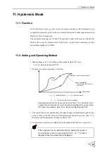
In the Hysteresis 2 mode, go and return waveforms changing with displacement are
sampled for High/Low Limit Comparisons of go measured values and differences
between go and return measured values (go - return) on the displacement points where
external pulses are input.
The operation is the same as in the Hysteresis mode except for the holding method and
the High/Low Limit Comparison method.
12-2. Setting and Operating Method
1. Sampling is the same as in the Hysteresis mode. (See "11-2. Setting and Operating
2. Measure the High and Low Limits.
・
Go measured value comparison: Uses the High Limit / Low Limit.
・
Between-go-and-return difference comparison: Uses the HI-HI Limit / LO-LO
Limit. (See"16-2-7. High Limit / Low Limit / HI-HI/LO-LO Mode / HI-HI Limit /
LO-LO Limit" P109.)
3. Pulse Input
Determine displacement points by the ON edges of HOLD 1 ~ 3 (See"4-3-2. Input
and Output Signals" P25.) For the set values of High and Low Limits with respect to
each Pulse Input, the target channels are fixed as
HOLD 1: operation ch, HOLD 2: operation ch+1, and HOLD 3: operation ch+2.
(When the operation ch is 31ch, the target channels are fixed as HOLD 1: 31ch,
HOLD 2: 0ch, and HOLD 3: 1ch.)
Also, the input / output specifications of each signal are the same as in Pulse Hold
(See "10-3-10. Pulse Hold" P62.) (The results of difference judgment are output when
the return displacement point=go pulse input displacement point.)
4. Start Sampling.
(See "9. Method of Starting Measurement" P43, and "16-2-9. Level Axis Select / Waveform
Start Level / Waveform Termination Level / Hold Start Level" P113.)

