9
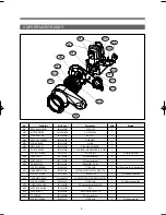
2. DRYER MOTOR ASS'Y
M03
M02
M01
M09
M14
M15
M08
M16
M13
M10
M11
M12
M05
M07
M04
M06
No.
Part Name
Part Code
Description
Qtt'y
Remark
M01
BRACKET MOTOR
3610608500
SGCC 2.0T
1
M02
MOTOR DRYER
36189L5D00
AC 120V 60Hz
1
M03
CLAMP MOTOR
3611206000
SK5 0.7T
2
M04
BRACKET IDLER AS
3610609100
DWR-WE31
1
M05
SPRING IDLER
3615115500
HSW3
1
M06
SPECIAL BOLT
3616039000
S18A M6x10(FLANGE)
1
M07
SWITCH MICRO
3619047500
UL. 16A 250AC HINGE LEVER. N-C 200G
1
-
SCREW TAPPING
7121301611
T2S PAN 3x16
2
For fixing micrd s/w
M08
CASE FAN F
3611144900
PP(Heat resisting)
1
M09
CASE FAN R
3611145000
PP(Heat resisting)
1
M10
GASKET PIPE
3612323200
EPDM(320*15*2.0t)
1
-
SCREW TAPPING
7112401411
T1 TRS 4x14
3
For fixing case fanr to bracket motor
M11
THERMOSTAT FAN
3619047900
UL.70ON.85OFF.125V/15A,250V/7.5A
1
-
SCREW TAPPING
7121300811
T2S PAN 3x8
2
For fixing thermostat fan
M12
THERMISTOR FAN
361AAAAC20
UL-DRYER.R40=26.065K.R90=4.4278K
1
-
SCREW TAPPING
7122401411
T2 TRS 4x14
1
For fixing thermistor fan
M13
IMPELLER FAN AS
3611886200
PP(Heat resBUSHING
1
M14
SPECIAL WASHER
3616039100
SPC
1
M15
SPECIAL NUT
3616039200
NUT HEX 3/8-24 UNF LH
1
M16
COVER FAN
3611428200
PP(Heat resisting)
1
-
SCREW TAPPING
7122401411
T2 TRS 4x14
2
For fixing cover fan
합본 svc manual 2008.5.6 6:21 PM 페이지10
Summary of Contents for KUD-WG33S
Page 1: ...JUL 2008 Service Manual Model KUD WG33S Gas Dryer ...
Page 8: ...1 DRYER CBINET ASS Y PartsListbyAss y 7 ...
Page 35: ...33 2 DIAGRAMA SECADORA DE GAS ...
Page 58: ...57 BLOCK DE TERMINALES 1 Remove cover terminal 2 Remove 3 screws sólo secadora eléctrica ...
Page 63: ...4 Switch de Puerta Presione los seguros y empuje hacia el frente ...


