29
TIP:
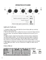
Before proceeding, take note of the original burner bypass screw placement.
ADJUSTING THE OVEN BURNER FLAME
1) Light the burner and turn the thermostat to the 500ºF position,
2) Allow the oven to heat up for approximately 20 minutes then rotate the knob to
the 450ºF position
NOTE:
The knob must be in the 450ºF position to access the by-pass screw
4) Remove the knob to gain to access to the thermostat by-pass.
5) Move the insulation to the side, away from the hole
6) Locate the access point for the thermostat by-pass screw - fig 1
7) Slowly screw the by-pass screw clockwise (approx 3/4 to one full rotation) until
you obtain a flame of approximately 1/6” (0.16 cm) in height.
DO NOT OVERTIGHTEN.
8) Once desired flame height is achieved
reattach the knob to the valve stem.
9) Following the conversion, set the oven
to 300ºF, fully open the door and firmly close door to verify the flame doesn’t ex-
tinguish. If the flame extinguishes the by-pass screw has been over adjusted and
needs to be
slightly
rotated counter clockwise, refer back to step 5 for re-adjust-
ment.
OVEN VALVE
The oven control has a flame safety device built into the body of the thermostat.
Presence of a gas ignition source (pilot) is verified by a flame safety probe. This
flame safety probe actuates the internal safety device to allow gas into the oven
burner when the oven is turned on. If there is a loss of gas ignition during opera-
tion, the flame safety device will close off gas flow to the oven burner and pilot.
The oven burner orifice is located on a brass injector stud at the rear of the oven
under the oven floor. This orifice is dedicated to the gas for which the oven is to be
used. The orifice is not adjustable. It must be changed completely to convert from
one gas to the other. DO NOT DISCARD THE UNUSED ORIFICE. It should be
saved in order to convert the range back to its original fuel.
ADJUSTING THE TOP BURNER AND OVEN FLAME
(continued)
fig 1
Summary of Contents for PRESTIGE UGP-20V PC1 B
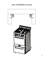
Page 21: ...21 WALL CLEARANCES continued ...
Page 46: ...UGP 20V PC1 S S WIRING DIAGRAM 46 ...
Page 54: ...NOTES 54 ...


