background image

U N I Q U E   U G P   1 3  


13

thinners) and blow it out with compressed air. Re-install and tighten 
burner orifice.


o


Replace burner.


Warning - DO NOT use a pin or wire when cleaning the 

burner orifice as damage can occur to the precision 

opening. This can cause damage to the refrigerator or 
create a fire hazard. It will also create extremely 
dangerous 
levels of carbon monoxide. 


o


Replace components in reverse order. 

o


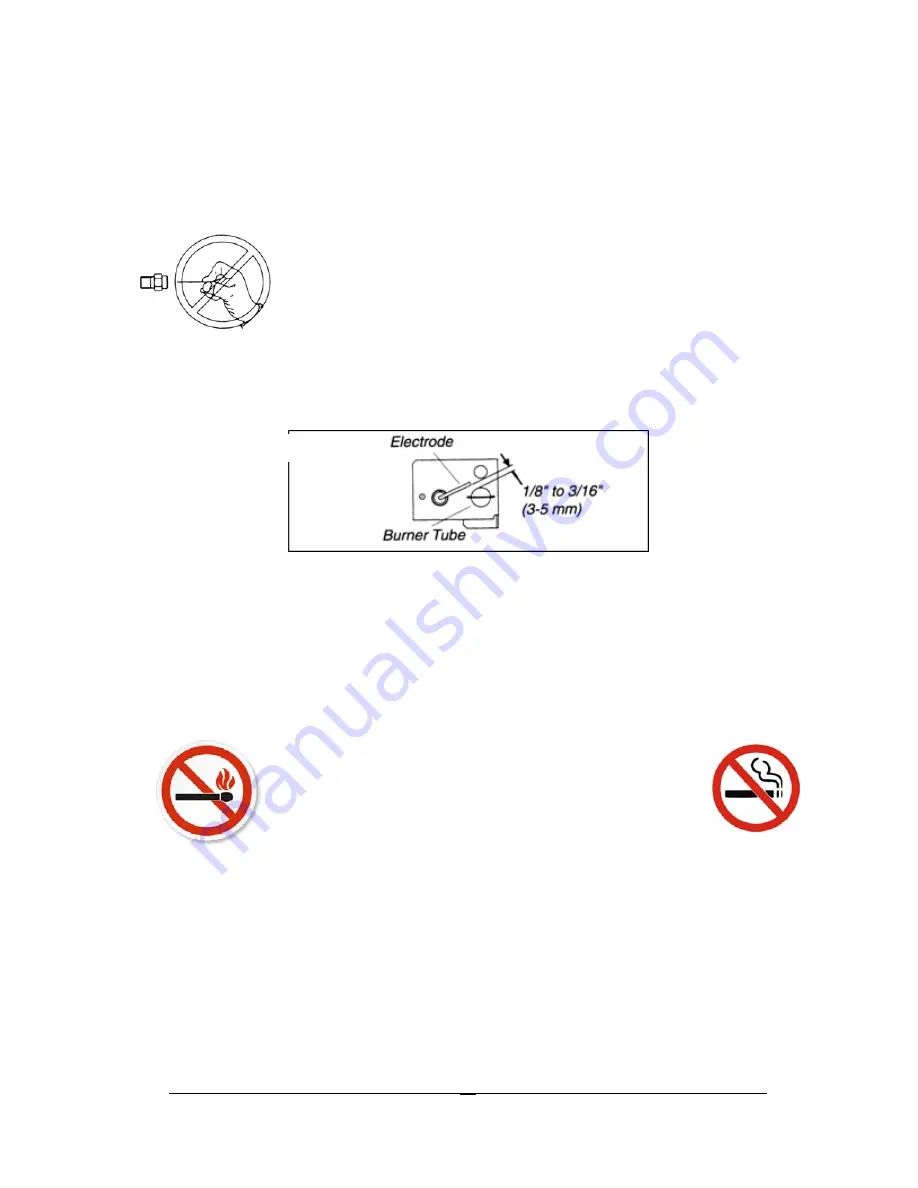
Be sure to reconnect the wire to the electrode. Check the electrode for 
proper location and gap. 

See Figure #8 


o


The inlet & outlet gas fittings on the refrigerator need to be checked for 
leaks. Apply a non corrosive bubble solution to the fittings and observe 
for leaks. The safety valve will not allow gas pressure to any connections 
between it and the burner orifice. These fittings must be checked while 
burner is in operation (gas flow will be present between safety valve and 
burner head). 


W

ARNING 


The safety shut-off 

(“E” button Fig. #5) 

must 

be manually depressed to allow gas pressure to flow to the 
burner orifice. Be sure to apply the leak check solution before 
depressing the safety shut–off. DO NOT allow any open 
flame, sparks, smoking, etc. in the area of the test. DO NOT 
depress safety shut-off for over 30 seconds. 


o


If leak occurs, correct problem, recheck with leak test solution then light 

the burner according to the instructions under 

G

ENERAL 

O

PERATING 

I

NSTRUCTIONS 


G

AS OPERATION

,


C

HAPTER 

3.


Fig# 8 

Summary of Contents for UGP 13

Page 1: ...ice or maintenance can cause injury or property damage Refer to this manual For assistance or additional information consult a qualified installer service agency or the gas supplier SAVE THESE INSTRUC...

Page 2: ...kill you Once unsafe levels of CO are detected an alarm will sound and the refrigerator will be shut off WARNING Actuation of this device indicates the presence of unsafe levels of carbon monoxide CO...

Page 3: ...Canada L6L 5L7 Ph 905 827 6154 Toll Free 1 877 427 2266 Fax 905 827 2027 www UniqueOffGrid com E mail info uniqueoffgrid com P P Pe e er r rs s so o on n na a al ll S S Se e er r rv v vi iic c ce e e...

Page 4: ...t Shield Installation 2 General Operating Instructions 3 How to Use the Refrigerator 3 Maintenance Service 4 Troubleshooting Suggested Spares 5 Carbon Monoxide Instructions CM Model 6 Door Removal and...

Page 5: ...s Products We hope you will consider us for future purchases PLEASE READ AND SAVE THESE INSTRUCTIONS This manual provides specific operation instructions for your model Use your refrigerator only as i...

Page 6: ...teration service or maintenance can cause injury or property damage Refer to this manual For assistance or additional information consult a qualified installer service agency or the gas supplier This...

Page 7: ...gas supply Where a flexible metal connector is used it must comply with local authorities and in Canada with the provisions of the current Standard CAN 1 6 10 Metal Connectors for Gas Appliances Howev...

Page 8: ...ome very warm To reduce heat build up we recommend providing an area for two air vents to circulate the air One placed 6 off the floor and the other at or above the appliance top Cold air return vents...

Page 9: ...e sure the refrigerator and any other high BTU appliances on your line are turned on when checking the gas pressure The appliance and its individual shut off valve must be disconnected from the gas su...

Page 10: ...not level liquid ammonia will accumulate in sections of the evaporator tubing This will slow the circulation of hydrogen and ammonia gas or in severe cases completely block it resulting in a loss of...

Page 11: ...thermostat knob to suit your needs after 8 hours of operation 6 The quantity of food in the refrigerator the frequency with which the refrigerator doors are opened and the room temperature will all af...

Page 12: ...ed and unventilated this is necessary to maintain the required low temperature for food storage The coldest areas in the refrigerator are under the cooling fins and at the bottom of the refrigerator T...

Page 13: ...t the rear of the refrigerator where it normally evaporates If heavy frost has built up on the cooling fins creating a lot of defrost water be aware that your water reservoir may overflow we suggest y...

Page 14: ...ize batteries operate the interior light The battery compartment is located on the exterior back of the fridge Shut Down Procedure A Turn gas valve knob C to the off position B If the refrigerator wil...

Page 15: ...refrigerator Always use a backup wrench when loosening and tightening this connection Cap the gas supply line and remove refrigerator Replacement is the reverse of removal Check all connections for ga...

Page 16: ...burner both require cleaning in the following manner o Remove cover from the burner housing o Disconnect the wire from the spark electrode o Remove the burner o Remove the wire and flue baffle from t...

Page 17: ...ly a non corrosive bubble solution to the fittings and observe for leaks The safety valve will not allow gas pressure to any connections between it and the burner orifice These fittings must be checke...

Page 18: ...baffle not inserted properly in flue tube 6 Improperly set thermostat See paragraph on thermostat In hot weather or heavy use the setting should be closer to Max than usual 7 Burner dirty Clean See S...

Page 19: ...mmonly used parts which are available Burner orifice Burner Electrode Thermocouple Piezo Igniter push button Baffle Contact your dealer or an authorized service center for parts and repairs as needed...

Page 20: ...technology that detects CO in a manner similar to the human body s response Please read this owner s manual carefully so you will have a better understanding of the effects of CO poisoning and the CO...

Page 21: ...combustion such as those emitted from appliances furnaces fireplaces and auto exhaust A CO Alarm is NOT A SUBSTITUTE for other combustible gas fire or smoke alarms This carbon monoxide alarm is desig...

Page 22: ...n an attached garage or adjacent to the residence For users in Canada follow the protocol in steps 1 and 2 below 1 Immediately move to fresh air outdoors or by an open door or window Check that all pe...

Page 23: ...ignal means and how they must exit the residence by themselves if necessary Decide on a meeting place a safe distance from your house and make sure all occupants understand where they should go and wa...

Page 24: ...at most of the fatal CO occurrences happen at night while people are sleeping and or while they are in the garage Early warning of CO is best achieved by the correct installation of CO alarms 5 2 This...

Page 25: ...operation of several fuel burning appliances competing for limited internal air Vent pipe connections vibrating loose from clothes dryers furnaces refrigerators or water heaters Obstructions in or un...

Page 26: ...correct orientation as noted on the inside of the battery door When installing the battery align the and battery terminals on the correct contacts The alarm will beep once indicating proper battery in...

Page 27: ...where you plan to gather after the alarm indicates the presence of carbon monoxide 7 0 ALARM SIGNALS 7 1 NORMAL OPERATION RED L E D flashes once every 30 seconds indicating that the alarm is powered...

Page 28: ...0 BATTERY REPLACEMENT NOTE IF TAMPER RESISTANT PIN HAS BEEN USED REFER TO STEP 6 7 UNDER INSTALLATION INSTRUCTIONS FOR REMOVAL INSTRUCTIONS See Figure 3 9 1 To replace the battery remove the alarm fr...

Page 29: ...ease the button The alarm will then test itself for proper operation and the RED L E D light will flash 4 6 times At completion of the self test the alarm will sound 2 patterns The alarm then resumes...

Page 30: ...e instructions NOTE All parts removed must be saved to do the re install the door Remove the hinge cover on the right top of the cabinet Remove the 4 bolts that hold the top hinge in place using a rat...

Page 31: ...to the left Remove the hinge cover from the upper left side one screw and transfer over to the right side Pop off the caps covering screws that are holding middle hinge in place and retain Unscrew the...

Page 32: ...inge Remove the 3 bolts that hold the bottom hinge in place using a ratchet tool with a 10 mm socket or a Phillips screwdriver Now loosely mount the bottom hinge to the left side of the cabinet with t...

Page 33: ...in close the door against the cabinet and the magnet in the door gasket will hold it in place Once you have the hinge bung fastened to the top left of the fridge door secure the middle hinge in place...

Page 34: ...ith the left side of the cabinet and gaskets all fit Also look directly at the front of the fridge and ensure the gap between the top of the fridge door and bottom of the freezer door is the same from...

Page 35: ...t setting the controls or when changing a setting wait 24 hours for the temperature to stabilize before making additional changes TEMPERATURE ADJUSTMENT Adjust temperature gradually move the knob in s...

Page 36: ...The fresh food compartment should be kept between 38 F and 40 F 3 3 C and 4 4 C with an optimum temperature of 38 F 3 3 C Avoid overcrowding the refrigerator shelves This reduces the circulation of a...

Page 37: ...nd freezer clean to prevent odour build up Wipe up any spills immediately and clean both sections at least twice a year Never use metallic scouring pads brushes abrasive cleaners or strong alkaline so...

Page 38: ...U N I Q U E U G P 1 3 34 Parts Diagram and List Interior of Fridge Chapter 9...

Page 39: ...U N I Q U E U G P 1 3 35 Burner Train Assembly CO Monitor Parts 32 33 34...

Page 40: ...H WIRE 9 UGP13 09 THERMOCOUPLE LEAD 10 UGP13 10 3 8 GAS INLET FITTING 11 UGP13 11 1 INLET GAS TUBE 12 UGP13 12 1 INLET FITTING 13 UGP13 13 1 THERMOSTAT 14 UGP13 57 ON OFF VALVE 14 1 UGP13 58 ON OFF KN...

Page 41: ...0 LEVELING FOOT 26 UGP13 51 CRISPER DRAWER 27 UGP13 52 TOP MIDDLE AND BOTTOM SHELVES 28 UGP13 53 INTERIOR LIGHT 29 UGP13 54 MIDDLE HINGE 30 UGP UNV PREMIUM CHIMNEY BRUSH FOR ALL PRODUCTS 31 UGP13 55 F...

Page 42: ...our and transportation charges will be the responsibility of the owner Coils replaced during the initial five year period will be warranted only for the remaining portion The Seller will have no oblig...

Page 43: ...TEN WARRANTY EXCEPT AS REQUIRED BY LAW INCLUDING BUT NOT LIMITED TO ANY WARRANTY OF MERCHANTABILITY OR FITNESS FOR A PARTICULAR PURPOSE OR AGAINST INFRINGEMENT OR ANY EXPRESS OR IMPLIED WARRANTY ARISI...

Reviews: