background image

U N I Q U E   U G P - 2 2  


24 


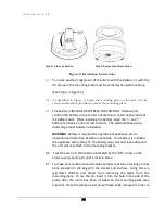
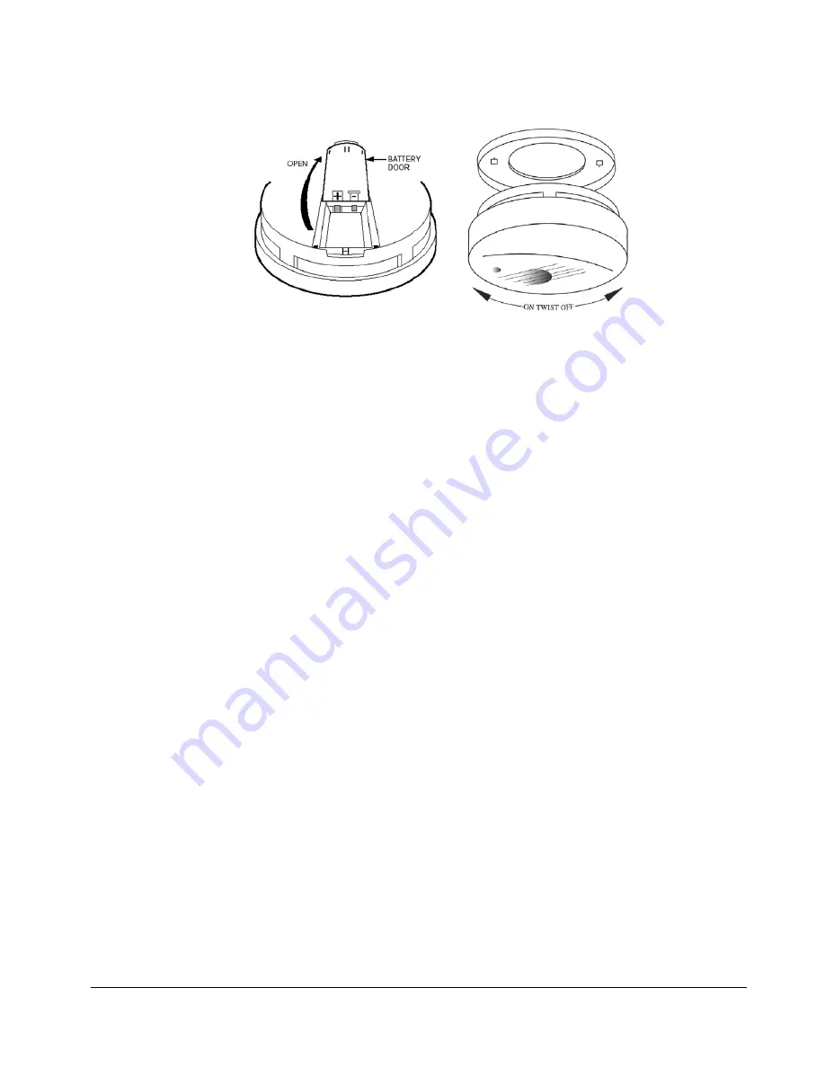
Step B:  Alarm Activation                                    Step C: Removal and Installation  


6.3  

To insure aesthetic alignment of the alarm with the hallway or wall, the 

UP arrow on the mounting plate must be vertical when wall mounting:  


(See Step A in Figure 2)   

 
6.4   As  described  in  Figure  2,  attach  the  mounting  plate  on  the  wall.  Use  the 

screws and anchors provided to secure the mounting plate.  

 
6.5 

The battery is INSTALLED REVERSED FOR SHIPPING.  Remove and 

reinstall the battery in the correct orientation as noted on the inside of 

the battery door.  When installing the battery, align the “+” and “-“ 

battery terminals on the correct contacts.  The alarm will beep once 

indicating proper battery installation. 

WARNING

: Battery is required for operation of appliance, alarm 

operation and detection of carbon monoxide.  If no battery is installed, 

the appliance will not stay lit. The battery door will not close easily and 

the unit will not attach to the mounting bracket. 


6.6    Twist the alarm in the direction indicated by the “ON” arrow on the 

alarm cover (see step D) until it locks in place. 

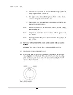
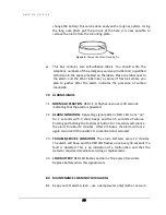
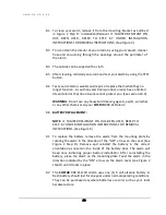
6.7   To make your carbon monoxide alarm tamper resistant, a locking pin has 

been  provided  in  the  bag  with  the  screws  and  anchors.    Using  this  pin 

will  deter  children  and  others  from  removing  the  alarm  from  the 

mounting plate.  To use the pin insert it into the hole in the side of the 

alarm  after  the  alarm  has  been  installed  on  the  mounting  plate  (See 

Figure 3).  Note the tamper resist pin will have to be removed in order to 

Figure 2: Installation Instructions  


Summary of Contents for UGP 22

Page 1: ...625 8 L 22 1 cu ft UGP 22 Propane Refrigerator OWNER S GUIDE serial number March 2016 ...

Page 2: ...rator Installation and Owners Manual The installation of the appliance must conform with local codes or in the absence of local codes to the national Fuel Gas Code ANSI Z233 1 and in Canada B149 2 Propane Storage and Handling Code ...

Page 3: ...as Products Ltd 2245 Wyecroft Road Oakville Ontario Canada L6L 5L7 Ph 905 827 6154 Toll Free 1 877 427 2266 Fax 905 827 2027 www UniqueOffGrid com E mail info uniqueoffgrid com Personal Service Knowledge makes us Personal Service Knowledge makes us Unique Unique ...

Page 4: ...llation 2 General Operating Instructions 3 How To Use The Refrigerator 3 Maintenance Service 4 Troubleshooting Suggested Spares 5 Carbon Monoxide Instructions CM Model 6 Door Reversal Removal Instructions 7 Temperature Controls Food Storage and Cleaning 8 Parts Warranty 9 ...

Page 5: ...ll consider us for future purchases PLEASE READ AND SAVE THESE INSTRUCTIONS This manual provides specific operation instructions for your model Use your refrigerator only as instructed in this manual These instructions are not meant to cover every possible condition and situation that may occur Common sense and caution must be practiced when installing operating and maintaining the appliance Pleas...

Page 6: ... or other flammable vapors and liquids in the vicinity of this unit or any other appliance Warning Improper installation adjustment alteration service or maintenance can cause injury or property damage Refer to this manual For assistance or additional information consult a qualified installer service agency or the gas supplier This product can produce Carbon Monoxide Carbon Monoxide has no odour a...

Page 7: ...supply Where a flexible metal connector is used it must comply with local authorities and in Canada with the provisions of the current Standard CAN 1 6 10 Metal Connectors for Gas Appliances However if the Local Authorities require a rigid gas supply connector the refrigerator should be located with sufficient space at the back for servicing or if located against a wall a removable panel of a mini...

Page 8: ...ides are open Fig 2 During hot humid weather this confined area will become very warm To reduce heat build up we recommend providing an area for two air vents to circulate the air One placed 6 off the floor and the other at or above the appliance top Cold air return vents with adjustable louvers work very well This will allow hot air to evacuate the area and assist in air flow across the fins simi...

Page 9: ...re of not more than 12 water column and no less than 11 water column Max setting Make sure the refrigerator and any other high BTU appliances on your line are turned on when checking the gas pressure The appliance and its individual shut off valve must be disconnected from the gas supply piping system during any pressure testing of that system at pressures in excess of psig In case detailed instru...

Page 10: ...ly begin loading the compartment The tubing in the evaporator section is specifically sloped to provide a continuous movement of liquid ammonia flowing downward by gravity through this section If the refrigerator is operated when not level liquid ammonia will accumulate in sections of the evaporator tubing This will slow the circulation of hydrogen and ammonia gas or in severe cases completely blo...

Page 11: ...this means flame is now lit Stop sparking and continue to hold gas button E down for an additional 10 seconds Release gas button fridge should now stay lit and the needle should remain in the green area 5 Once all the above has been done and you are ready to re start your fridge for use leave the thermostat button at 4 Setting the thermostat to 4 will allow the fridge to get to optimum cooling tem...

Page 12: ...rmostat closes its main valve and the burner runs continuously at the bypass rate or pilot flame counter clockwise turn 2 Max Setting of the Thermostat In gas operation the thermostat allows the burner to remain on high flame continuously clockwise turn 3 The thermostat can be adjusted between Max and Defrost to obtain the desired fridge temperature When the thermostat reaches the set temperature ...

Page 13: ... it in covered dishes containers plastic bags or wrapped in aluminum foil Defrosting Frost will gradually accumulate inside the refrigerator and freezer surfaces It must not be allowed to grow too thick as it acts as an insulator and adversely affects the refrigerator performance Check the formation of frost every week and when it exceeds 3 8 thick defrost the refrigerator It will not hurt the fri...

Page 14: ...rigerator is usually done after it is defrosted or put into storage To clean the interior liner of the refrigerator use lukewarm dish soap solution Use only warm water to clean the finned evaporator gasket ice trays and shelves Never use strong chemicals or abrasives to clean these parts as the protective surfaces will be damaged It is important to always keep the refrigerator clean Dish soap is r...

Page 15: ...oval Check all connections for gas leaks Refer to Chapter 2 INSTALLATION PERIODIC MAINTENANCE Before working on refrigerator shut off the gas supply Disconnect the gas line at the rear of the refrigerator Always use a back up wrench when loosening and tightening this connection Cap the gas supply line and remove refrigerator Replacement is the reverse of removal Check all connections for gas leaks...

Page 16: ...rner flame for proper appearance The flame should be light blue with no yellow at the tip See figure 6 The LP gas pressure should be checked and the main regulator readjusted if pressure is incorrect The correct operating pressure is 11 W C water column Inspect the flue baffle it should be clean and free of soot Any soot formation indicates improper functioning of the burner The flue and burner bo...

Page 17: ...tor or create a fire hazard It will also create extremely dangerous levels of carbon monoxide o Be sure to reconnect the wire to the electrode Check the electrode for proper location and gap See figure 8 o The inlet outlet gas fittings on the refrigerator need to be checked for leaks Apply a non corrosive bubble solution to the fittings and observe for leaks The safety valve will not allow gas pre...

Page 18: ...E U G P 2 2 14 o If leak occurs then allow ten minutes to dissipate from the burner area Fix leak then light the burner according to the instructions under GENERAL OPERATIONG INSTRUCTIONS GAS OPERATION CHAPTER 3 ...

Page 19: ...frost 5 Flue baffle not inserted properly in flue tube 6 Improperly set thermostat See paragraph on thermostat In hot weather or heavy use the setting should be closer to Max than usual 7 Burner dirty Clean See Section MAINTENANCE SERVICE CHAPTER 4 PERIODIC MAINTENANCE 8 LP gas pressure low at burner Regulator pressure must not drop below 11 inches W C water column CHAPTER 2 GAS CONNECTION 9 Burne...

Page 20: ... parts which are available Burner orifice Burner Electrode Thermocouple Safety valve thermostat Piezo igniter push button Baffle Contact your dealer or an authorized service center for parts and repairs as needed Quote Model Serial See CSA rating serial plate on inside left wall ...

Page 21: ...ngratulations as you have taken steps to help ensure the health and safety of you and your family We are proud to offer you our unique patented CO Sensor technology that detects CO in a manner similar to the human body s response Please read this owner s manual carefully so you will have a better understanding of the effects of CO poisoning and the COSTAR 9RV SSO alarming device in conjunction wit...

Page 22: ...CARBON MONOXIDE POISONING indicate that while victims are aware they are not well they become so disoriented they are unable to save themselves by either exiting the building or calling for assistance Also young children and household pets may be the first affected Your CO alarm is designed to detect the toxic CO fumes that result from incomplete combustion such as those emitted from appliances fu...

Page 23: ...at steps 1 3 and call a qualified technician ____ ______ to investigate for sources of CO from fuel burning equipment and appliances motor vehicles or other sources and inspect for proper operation of this equipment If problems are identified during this inspection have the equipment serviced immediately Note any combustion equipment not inspected by the technician and consult the manufacturers in...

Page 24: ...ainst which CO detection may not be effective such as gas leaks or explosions The ultimate responsibility for protection against toxic CO fumes rests solely on you Installing CO detectors is just the first step in protecting your family from toxic CO poisoning We also suggest that you create an effective comprehensive safety program as outlined below 3 1 Install CO detectors properly following the...

Page 25: ...cated installed and maintained this CO alarm is designed to provide early warning of developing poisonous CO conditions at a reasonable cost This alarm monitors the air and when it senses CO it activates its built in alarm It can provide precious time for you and your family to escape from your residence before CO can seriously injure or kill However such an early warning is possible only if the a...

Page 26: ...oms In very cold or very hot environments or in unheated buildings or outdoor rooms where the temperature can go below or above the operating range of the alarm Temperature limits for proper operation are 20 F to 120 F 29 C to 49 C Operating Humidity is 10 95 RH Good ventilation is recommended when household cleaning supplies or similar contaminants are used 5 4 CONDITIONS WHICH CAN RESULT IN TEMP...

Page 27: ... fireplace etc 5 4 3 Temperature inversions which can trap exhaust gasses near the ground 5 4 4 Car or generator idling in an open or closed area garage or near a home 6 0 INSTALLATION INSTRUCTIONS READ CAREFULLY BEFORE INSTALLING ALARM CAUTION THIS UNIT IS SEALED THE COVER IS NOT REMOVABLE 6 1 Select proper location See section 5 0 6 2 A mounting plate is provided on the back of the alarm Remove ...

Page 28: ... proper battery installation WARNING Battery is required for operation of appliance alarm operation and detection of carbon monoxide If no battery is installed the appliance will not stay lit The battery door will not close easily and the unit will not attach to the mounting bracket 6 6 Twist the alarm in the direction indicated by the ON arrow on the alarm cover see step D until it locks in place...

Page 29: ...shes once every 30 seconds indicating that the alarm is powered 7 2 ALARM CONDITION Repeating signal pattern RED LED turns on for 2 seconds with 4 short beeps and then 5 seconds of silence Pushing and holding the test reset button for 3 seconds will silence the alarm for about 4 minutes After 4 minutes the alarm will once again sound until the unsafe CO concentration is reduced 7 3 TROUBLE SERVICE...

Page 30: ... cleaning agents paints varnishes or any other chemical on your COSTAR 9RV SSO alarm 9 0 BATTERY REPLACEMENT NOTE IF TAMPER RESISTANT PIN HAS BEEN USED REFER TO STEP 6 7 UNDER INSTALLATION INSTRUCTIONS FOR REMOVAL INSTRUCTIONS See Figure 3 9 1 To replace the battery remove the alarm from the mounting plate by rotating the alarm in the direction of the OFF arrow on the cover See Figure 2 Step D Rem...

Page 31: ...hort beep is heard approximately three seconds Release the button The alarm will then test itself for proper operation and the RED L E D light will flash 4 6 times At completion of the self test the alarm will sound 2 patterns The alarm then resumes normal operation WARNING THIS TEST PROCEDURE WILL TURN OFF THE APPLIANCE ONCE THE ALARM RESUMES NORMAL OPERATION RE LIGHT APPLIANCE FOLLOWING LIGHTING...

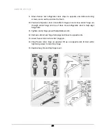
Page 32: ... Unscrew center hinge pin using adjustable wrench and save for reassembly Ensure plastic washer stays on hinge pin 4 Lift refrigerator door off of bottom hinge and set aside 5 Remove center hinge and shim by removing inside screw and loosening two outside screws enough to allow hinge and shim to slide out Tighten screws Loosen two outside screws on opposite side of refrigerator remove inside screw...

Page 33: ...ge pin through center hinge into top of door Close refrigerator door to help align hinge hole 11 Tighten center hinge pin with adjustable wrench 12 Remove cabinet and hinge hole plugs and move to opposite side 13 Lower freezer door onto center hinge pin 14 Close freezer door Have an assistant lift up on opposite side of door while tightening screws to install top hinge 15 Replace toe grille and to...

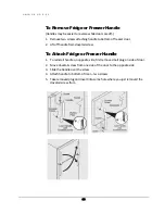
Page 34: ...off handle from dovetail screw To Attach Fridge or Freezer Handle 1 To reinstall handle on opposite side first remove small plug on side of door 2 Move dovetail screw from one side of the door to the opposite side 3 Slide the handle over the screw 4 Attach handle to bottom of door two screws 5 Take removed plug and insert into same hole where you just removed the dovetail screw from ...

Page 35: ...DJUSTMENT Adjust temperature gradually move the knob in small increments allowing the temperature to stabilize For colder interior temperatures turn the knob clockwise For warmer interior temperatures turn the knob towards counter clockwise Adjusting the refrigerator control will change temperatures in both compartments Remember there is no fan to circulate the air in the refrigerator and freezer ...

Page 36: ...the shelves remove all food Crispers Deli Drawers The crispers located under the bottom refrigerator shelf are designed for storing fruits vegetables and other fresh produce Wash items in clean water and remove excess water before placing them in the crispers Items with strong odors or high moisture content should be wrapped before storing ...

Page 37: ...rapped securely so leakage and contamination of other foods or surfaces does not occur FROZEN FOOD STORAGE The freezer compartment should be kept at 8 6 F 13 C at a 77 F 25 C room ambient A freezer operates most efficiently when it is slowly loaded to 2 3 full PACKAGING FOODS FOR FREEZING To minimize dehydration and quality deterioration use aluminum foil freezer wrap freezer bags or airtight cont...

Page 38: ...allic scouring pads brushes abrasive cleaners or strong alkaline solutions on any surface Do not wash any removable parts in a dishwasher When moving the refrigerator pull straight out You must turn gas off at source or have adequate flex line to move refrigerator Do not shift the refrigerator from side to side as this may tear or gouge the floor covering and damage the gas supply line Damp object...

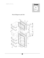
Page 39: ...U N I Q U E U G P 2 2 35 Parts Diagram and List Chapter 9 ...

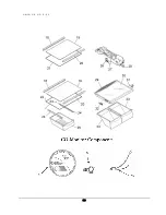
Page 40: ...U N I Q U E U G P 2 2 36 ...

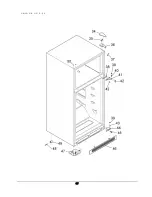
Page 41: ...U N I Q U E U G P 2 2 37 ...

Page 42: ...U N I Q U E U G P 2 2 38 Burner Train Assembly UGP 22 ...

Page 43: ... STAINLESS STEEL 3 UGP22 09 FREEZER DOOR BLACK 4 UGP22 10 CAP WHITE 4 UGP22 11 CAP BLACK 5 UGP22 12 HANDLE SCREW 6 UGP22 13 HANDLE SCREW 7 UGP22 14 FREEZER FRIDGE DOOR HANDLES WHITE 7 UGP22 15 FREEZER FRIDGE HANDLES BLACK 7 UGP22 16 FREEZER FRIDGE HANDLES STAINLESS STEEL 8 UGP22 17 SET SCREW 9 UGP22 18 DOOR STOP WHITE FREEZER 9 UGP22 19 DOOR STOP BLACK FREEZER 9A UGP22 20 DOOR STOP WHITE FRIDGE 9A...

Page 44: ...REW FREEZER AND FRIDGE HANDLES 18 UGP22 34 TRIM SHELF REAR 19 UGP22 35 GLASS SHELF 20 UGP22 36 TRIM SHELF FRONT 21 UGP22 37 FRAME SHELF 22 UGP22 38 FRAME SHELF HOLDS MEAT DRAWER 23 UGP22 39 HANGER SCREWS 24 UGP22 40 HANGER RAILS MEAT DRAWER 25 UGP22 41 MEAT DRAWER 26 UGP22 42 LIGHT SOCKET 27 UGP22 43 LED BULB 28 UGP22 44 LIGHT SWITCH 29 UGP22 45 COVER CRISPER PAN 30 UGP22 46 INSERT PAN COVER GLASS...

Page 45: ...INGE BLACK 42 UGP22 61 MIDDLE HINGE SCREWS 43 UGP22 62 BOTTOM HINGE PIN 44 UGP22 63 BOTTOM HINGE CHROME 44 UGP22 63 BOTTOM HINGE BLACK 45 UGP22 64 BOTTOM HINGE SCREWS 46 UGP22 65 GRILL WHITE 46 UGP22 66 GRILL BLACK 47 UGP22 67 ROLLER ASSEMBLY FRONT 48 UGP22 68 RIVET FLAT HEAD 49 UGP22 69 ROLLER REAR 50 UGP22 70 PLUG WHITE 50 UGP22 71 PLUG BLACK 51 UGP 9RV SS0 CO DETECTOR 9RV SSO 52 QMP INTERRUPTER...

Page 46: ...INLET GAS TUBE 60 UGP1518 4 OUTLET GAS TUBE 61 UGP18 56 PEIZO IGNITOR 62 UGP18 57 FLAME INDICATOR 63 UGP1518 9 SAFETY VALVE 64 UGP1518 2 KNOB THERMOSTAT 65 UGP1518 1 ON OFF VALVE 66 UGP1518 6 INLET FITTING 67 UGP1518 8 PIPE ON OFF VALVE TO THERMOSTAT CONTROL 68 UGP1518 7 THERMOSTAT CONTROL 69 UGPSPBLOCK SINGLE PRONG INTERRUPTER BLOCK 70 UGP1518 3 OUTLET FITTING ...

Page 47: ...ue Gas Products Ltd and the Seller labour and transportation charges will be the responsibility of the owner Coils replaced during the initial five year period will be warranted only for the remaining portion The Seller will have no obligation under this warranty with respect to conditions unrelated to the material or workmanship of this refrigerator Such unrelated conditions include without limit...

Page 48: ...NTY ARISING OUT OF TRADE USAGE OR OUT OF A COURSE OF DEALING OR COURSE OF PERFORMANCE UNIQUE GAS PRODUCTS LTD has not authorized any other party to extend any other warranties in connection with the sale of the product and will not accept responsibility for any statements representations or warranties made by any other person This limited warranty does not cover 1 9 volt alkaline battery 2 product...

Reviews: