Operation Manual
IMPORTANT
Page 1: ...Operation Manual IMPORTANT...
Page 2: ...Raider GMP Manual 03 06 2023 1 WE ARE HERE TO ASSIST For parts and service Have Questions Contact us UNIS SERVICE CENTER Tel 972 241 4263 Email service unispartsandservice com www unispartsandservice...
Page 3: ...MPORTANT SAFETY INSTRUCTIONS 3 1 SPECIFICATIONS 5 2 CONTENTS OF THE ACCESSORY KIT 6 3 PART NAME 7 4 SET UP INSTALLATION 8 5 HOW TO PLAY 22 6 GAME OPTION 23 7 TROUBLESHOOTING 27 8 MAINTENANCE INSPECTIO...
Page 4: ...ctions for future reference Use this product only as described in this manual Other uses not recommended may cause fire electric shock or personal injury Unplug the game from the outlet when not in us...
Page 5: ...direct sunlight or places subject to extremely hot or cold temperatures to ensure that it is used within the specified operating range Places where inflammable gas may be present or in the vicinity of...
Page 6: ...consumption 600W Dimension H90 35 W60 51 D63 03 in H2295 W1537 D1601 mm Weight Approximately 771 lb 350kg Model No C 743 Part No S187 NOTICE After turning off the game please wait at least 1 minute b...
Page 7: ...PEC Picture Qty 1 S187 0710 00 SJPJ 10 Manual 1 2 S187 0709 00 SJPJ 09 Power cord 1 3 S187 0711 00 SJPJ 11 Key 4 4 S187 0705 00 SJPJ 05 Fuse 2 5 S187 0701 00 SJPJ 01 Motor plate 1 6 S187 0702 00 SJPJ...
Page 8: ...Space Raider GMP Manual 03 06 2023 7 3 PART NAME Key Components Marquee Play field Turntable Play instruction Display Button...
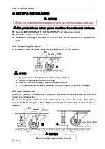
Page 9: ...ful not to damage the machine during transport Always unplug the game before moving Keep the machine in upright position during transport For longer distance transport package the game properly to pre...
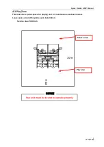
Page 10: ...9 4 3 Play Zone This machine requires space for playing and for maintenance as shown below Leave space around the game upon installation Service area 500 mm Service area Play area Your unit must be l...
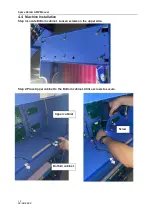
Page 11: ...Manual 03 06 2023 10 4 4 Machine Installation Step 1 Locate Bottom cabinet Loosen screws on the upper side Step 2 Place Upper cabinet to the Bottom cabinet Utilize screws to secure Upper cabinet Botto...
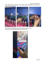
Page 12: ...ute these connectors to the bottom cabinet through the hole Connect the connectors as shown below Step 4 Place Side fixing plate to the Cabinet Utilize screws to secure Note It is the same installatio...
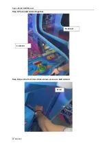
Page 13: ...Space Raider GMP Manual 03 06 2023 12 Step 5 Place L R cabinet together Step 6 Open the front door Utilize screws to secure L R cabinet L cabinet R cabinet Screw...
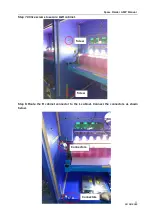
Page 14: ...e Raider GMP Manual 03 06 2023 13 Step 7 Utilize screws to secure L R cabinet Step 8 Route the R cabinet connector to the L cabinet Connect the connectors as shown below Screw Screw Connectors Connect...
Page 15: ...Space Raider GMP Manual 03 06 2023 14 Step 9 Install L R side upper plate to the top of the cabinet Utilize fixing plate and screws to secure L R side upper plate L R side upper plate Screws Screws...
Page 16: ...inside through the hole Connect the connector Step 11 Locate Bonus Marquee Install Fixing plate to the Bonus assembly Step 12 Install LOGO marquee POP plate and fixing plate to the Bonus assembly Con...
Page 17: ...plate to the top of the cabinet Utilize screws to secure a bit DO NOT TIGHTEN Step 14 Install Bonus assembly to the Cabinet Secure the Bonus assembly fixing plate Bonus assembly fixing plate Bonus ass...
Page 18: ...ider GMP Manual 03 06 2023 17 Step 15 Connect the Bonus assembly connectors Step 16 Locate Back PC decal Install Back PC decal fixing plate V H together Fixing plate H Fixing plate V Bonus assembly co...
Page 19: ...nstall Back PC decal to the Back PC decal fixing plate V H Step 18 Install Back plate to the fixing plate Step 19 Install Back PC decal to the back of the Bonus assembly Utilize screws to secure Back...
Page 20: ...Space Raider GMP Manual 03 06 2023 19 Step 20 Install Top light plate to the back of the Marquee Utilize screws to secure Step 21 Utilize screws to secure L R top light plate Top light plate Screws...
Page 21: ...Space Raider GMP Manual 03 06 2023 20 Step 22 Connect the connectors Finish Connectors Connectors...
Page 22: ...to assure that all wiring voltages are confirmed prior to installation of card reader All warranties are void if not properly installed resulting in logic board damage Important This game is pre wire...
Page 23: ...okens 5 3 Shoot tokens through the slots to earn points and light up the letter 5 4 Light up all 4 letters S H I P to move up the levels and win more points 5 5 Shoot tokens through the UFO slot for a...
Page 24: ...rntable arrow test Machine test Parameters Options shows in the shield 2 display Option value shows in the shield 1 display Audit shows in the Bottom display Left side show settings Right side shows b...
Page 25: ...ge settings may cause the machine to be faulty C19 Turntable score 1 10 800 50 C20 Turntable score 2 10 800 200 C21 Turntable score 3 10 800 100 C22 Turntable score 4 10 800 300 C23 Turntable score 5...
Page 26: ...s 200 Level 2 bonus 30 tickets Level 1 bonus 20 tickets UFO Bonus 100 Level 1 bonus 20 tickets S H I P S H I P 6 20 16 12 12 16 20 8 Pattern 1 about 25 tickets per coin Blue spaceship side Red spacesh...
Page 27: ...tickets UFO Bonus 150 Level 1 bonus 20 tickets S H I P S H I P 10 25 18 16 16 18 25 10 6 3 Test Testing Machine Options Meanings Description H00 Shoot tokens test Press Blast button to test H01 Ticket...
Page 28: ...cable problem Reconnect the audio cable or change it PC crash Restart or system recovery Driver problem Restart the audio driver Note After replacing component from PC except for RAM and replacing mo...
Page 29: ...w is offset E05 No coin Launching coin motor failure Replace launching coin motor Keep giving out coins Launching coins detect sensor is faulty Replace launching coin detect sensor E06 No tickets out...
Page 30: ...ote Please contact with UNIS before update Step 1 Copy Downloader software to the desk Step 2 Double click the Downloader software will see below interface click circled words which is to connect the...
Page 31: ...ual 03 06 2023 30 Step 4 Connect the programmer with computer via connection cable press No 2 blue button for several seconds until below image is showed on screen Step 5 Click Get image file from clo...
Page 32: ...2023 31 Step 6 Powering on programmer with an adapter or charger connect it with main board via programming cable as below picture shows No 1 and No 2 blue button is to select correct program No 3 blu...
Page 33: ...condition 3 Check the machine regularly for dust and clean when necessary Note Parts and components require preventative maintenance to maintain proper operation 8 2 Handling Precautions When installi...
Page 34: ...2 4 S187 0305 00 25600000116 Turntable decal 2 5 S187 0644 00 GMP WGJ27 Glass 2 6 S187 0314 00 25600000077 Header PC 1 7 S187 0601 00 GMP LED01 Header white light 1 8 S187 0316 00 25600000093 Side whi...
Page 35: ...echanism bracket 1 2 S187 0501 00 XZH230222 001 Bearing plate 6 3 S187 0507 00 XZH230222 007 Motor front rolling nylon 1 4 S187 0509 00 XZH230222 009 Mid rolling nylon 1 5 S187 0508 00 XZH230222 008 B...
Page 36: ...Space Raider GMP Manual 03 06 2023 35 9 3 Decal Part No Part No Code No Name Qty 1 S187 0301 00 20511605D019 Control panel decal 2 2 S187 0329 00 20541804C018 Door decal 2 1 2...
Page 37: ...Space Raider GMP Manual 03 06 2023 36 No Part No Code No Name Qty 1 S187 0303 00 25600000111 Upper PC board 2 2 S187 0304 00 25600000112 Bottom PC board 2 1 2...
Page 38: ...Space Raider GMP Manual 03 06 2023 37 1 2 3 4 5 6 7 8...
Page 39: ...0308 00 25600000037 Light plastic 2 4 S187 0305 00 25600000116 Turntable decal 2 5 S187 0307 00 25600000036 Cabinet side plastic 2 6 S187 0307 00 25600000036 Cabinet side plastic 2 7 S187 0309 00 2560...
Page 40: ...l 03 06 2023 39 No Part No Code No Name Qty 1 S187 0332 00 20541804C024 Nameplate 1 2 S187 0333 00 20541804C025 Warning decal 2 1 S187 0334 00 20541804C026 Warning decal 3 1 S187 0335 00 20541804C027...
Page 41: ...D05 Top spotlight 2 6 S187 0606 00 GMP LED06 Control panel light 2 7 S187 0607 00 GMP LED07 Bottom light 2 8 S187 0608 00 GMP LED08 Turntable light 2 9 S187 0609 00 GMP LED09 Prizing light 2 10 S187 0...
Page 42: ...41 No Part No Code No Name Qty 1 S187 0651 00 GMP WGJ34 L R motor 2 2 S187 0633 00 GMP WGJ16 White wheel 2 3 S187 0635 00 GMP WGJ18 Black wheel 2 4 S187 0637 00 GMP WGJ20 L R sensor 4 5 S187 0629 00 G...
Page 43: ...MP Manual 03 06 2023 42 No Part No Code No Name Qty 1 S187 0620 00 GMP WGJ03 Red button 8 S187 0621 00 GMP WGJ04 Counter 4 2 S187 0627 00 GMP WGJ10 Ticket dispenser 2 3 S187 0628 00 GMP WGJ11 Coin mec...
Page 44: ...WGJ32 Power supply 24V 5V 1 3 S187 0649 00 GMP WGJ32 Power supply 24V 5V 1 4 S187 0410 00 ZJ230222 010 Goal sensor board 2 5 S187 0411 00 ZJ230222 011 Main control board 2 6 S187 0407 00 ZJ230222 007...
Page 45: ...speaker 1 S187 0623 00 GMP WGJ06 4 speaker net 1 3 S187 0408 00 ZJ230222 008 Control panel display coin 2 4 S187 0409 00 ZJ230222 009 Control panel display ticket 2 5 S187 0403 00 ZJ230222 003 Turntab...
Page 46: ...Space Raider GMP Manual 03 06 2023 45 1 2 3 4 5 6 7...
Page 47: ...evel display 4 2 S187 0406 00 ZJ230222 006 Level light board 12 3 S187 0404 00 ZJ230222 004 UFO display 8 4 S187 0402 00 ZJ230222 002 SHIP light board 4 5 S187 0410 00 ZJ230222 010 Goal sensor board 2...
Page 48: ...5 6 12V 1 2 3 4 5 P2 Bonus display P3 P1 12V XH 5P XH 9P XH 6P 6 7 8 9 1 2 3 4 5 12V P4 4 Square light 1 2 3 4 5 12V P4 4 Square light 1 2 3 4 12V 1 2 3 4 12V 1 2 3 4 12V 1 2 3 4 12V 1 2 3 4 12V 1 2...